
The worldwide market for switchgear is estimated to be USD 90.9 billion. Due to trends in renewable energy-based capacity addition it is expected grow in the coming years. The APAC region with countries like China, India, Japan and Australia are expected to perform at the highest growth rates.
NESMA is the switchgear association representing many of Australia’s Manufacturers has made strong calls for local companies aligning to the latest quality and compliance standards. This includes the replacement of the currently governing manufacturing requirements AS/NZS 3439 which was introduced in 1998 for low voltage switchboards after May 2021. This is important to drive innovation and to further improve efficiency in power control and distribution.
There are 2 key groups to consider – Construction-related and Performance-related aspects.
Construction-related aspects include:
- degree of protection of enclosures (#2), [protection of persons against hazardous events etc.]
- clearances (#3) and creepage distances (#4) [measuring creepage distances and clearances in standard IEC 60664-1]
- integrity of protective circuit (#6)
Performance related aspects include:
- short circuit withstand strength (#11) [for above 17kA is the resistance of busbars and their support], breaking and protection of devices and enclosure to thermal and electrodynamic stresses)
- temperature rise limits and tests (#10) (to proof the ability to carry rated current)
- dielectric properties insulation frequency (#9) [of 50Hz and in the form of voltage waves simulating a lightning strike],
- electromagnetic compatibility (#14)
- mechanical operation (#13)
Switchgears can be divided into Low Voltage switchgears (up to 1kV), Medium Voltage Switchgear (2-36kV) and High Voltage Switchgear (above 36kV). Therefore, similar tests are conducted when making Medium and High Voltage Switchgear according to the international standard IEC 62271-100/200.
Where does computer modeling and simulation fit?
In most cases 3D data is required for manufacturing and therefore widely available. Computer simulation is built on top of those models only adding material properties and physics to the geometry. It can help engineers and designers to (1) maintain compliance during the design process and (2) later replicate switchgear tests.
Assessment of switch gear systems under temperature cycling (#10). The maximum temperature of the copper busbars in a switchboard is 105 degrees Celsius absolute above the ambient temperature in which the gear is operating. It is easy to perform temperature predictions before the switchgear system is built. This improves the lifespan of the gear and reduces the chance of overheating.
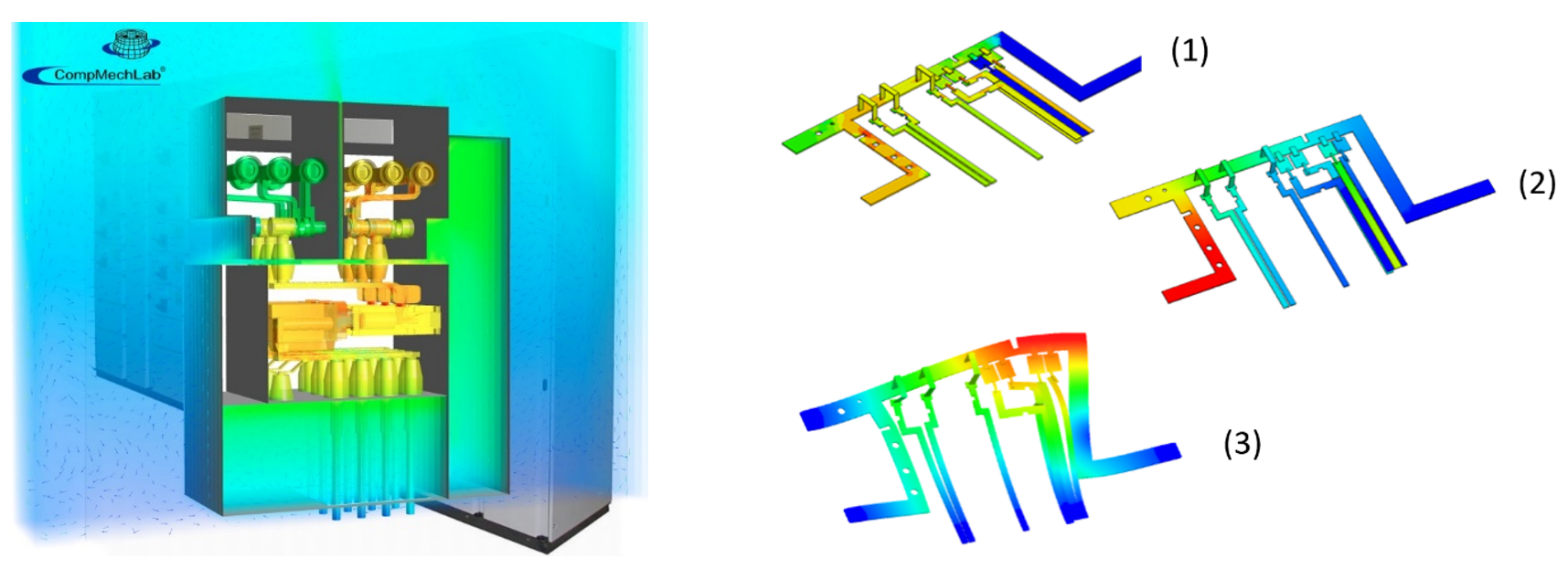
Fig.1: Virtual Temperature Rise Tests of switchgear systems including BusBar behavior: losses (1), thermal performance (temperature distribution (2)) and resulting deformations (3). The simulation takes the temperature in the environment and, if required solar radiation into account and differentiates between elastic and plastic deformations and includes mounting structures.
To test the degree of protection of enclosures (#2) LEAP has established a simulation workflow that is based on the IEEE 1584 Arc Flash Calculation analysis process for Low- and Medium Voltage Switchgear Systems. It provides engineers with a test procedure that evaluates the mechanical integrity of the switchgear system against hazardous event like an arc fault.
Fig.2:Enclosure resistance during an arcing event. Simulation can visualise the distribution of ionized gas (left-hand side) and mechanical stresses, mechanical strains and deformations of the enclosure.This method is valid for Voltages for 3-phase systems in the range of 208V-15 kV at a frequency of f= 50Hz/60Hz and a bolted fault current Ibf=700 A-106 kA.
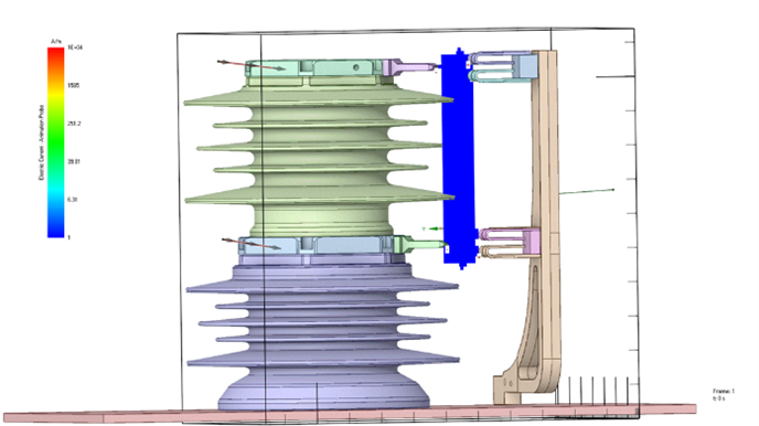
The compliance with correct clearances (#3) and creepage distances (#4) and dielectric properties for insulation (#9) can be assessed using a new workflow that combines full-wave electromagnetics and non-linear chemistry of air. Many CAD tools have features that measure distances between parts of different polarities and between live parts and the exposed conductive parts effectiveness and integrity of protective circuit. LEAP can help with a workflow that can show where an arc will form and therefore lets you adjust the geometry before building the switchgear and conducting physical tests.
Fig.3: Identify location of arc formation based on fields, geometry and quantify current within arc. The model includes effects of non-linear air chemistry and therefore lets the engineer adjust air pressure and humidity.
The same workflow can be applied for moving mechanisms like switches to calculate the correct current waveforms during activation.
This allows to predict radiated emissions from the switch in form of radiated power in Far Fields to look at EMC aspects.
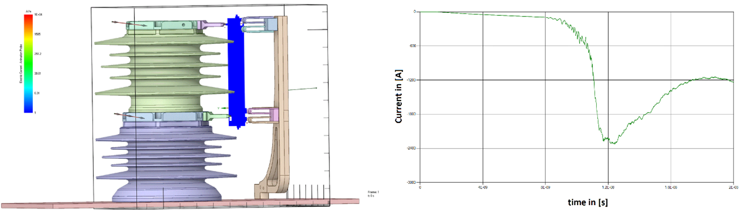
Fig.4: the switch is activated mechanically. Goal is to reproduce the current waveform during the switching process.
How to get started with this workflow?
Today we’ve shown you how simulation is an excellent way of making sure your switchgear is functioning to code and not causing any harm. LEAP’s simulation based workflow incorporates a solution for each of the following concepts:
- short circuit withstand strength (#11)
- degree of protection of enclosures (arc fault) (#2)
- Temperature Rise Tests (#10)
- Clearances (#3) and Creepage Distances (#4), Dielectric properties insulation (#9)
- electromagnetic compatibility EMC (#14)
Our methodologies and workflows are based on IEC 61439 and can be utilised either in-house at your company, or via a consultancy project in conjunction with LEAP. To get started or discuss your project, click here to start talking with LEAP’s electromagnetics team.