
In February 2014, Curtin Motorsport Team’s Frame & Body Technical Lead Nisarg Thakrar and Chassis Thesis Project Lead John Christensen conducted torsional stiffness validation testing on the team’s 2012 chassis. The purpose of this physical testing was to determine the chassis’ actual torsion stiffness value and to validate the results predicted through FEA simulations performed in ANSYS R14.5. Indirectly, this analysis could potentially be used to help the team’s further investigations into whether torsional stiffness has any noticeable effect on the handling characteristics of a Formula SAE race car under accelerating, braking and cornering loads. It is known that the torsional stiffness of a race car chassis affects the ability to tune the suspension. Cornell (2002) plotted overall vehicle stiffness…
Archives
Designing Quieter Products With Computer Aided Engineering
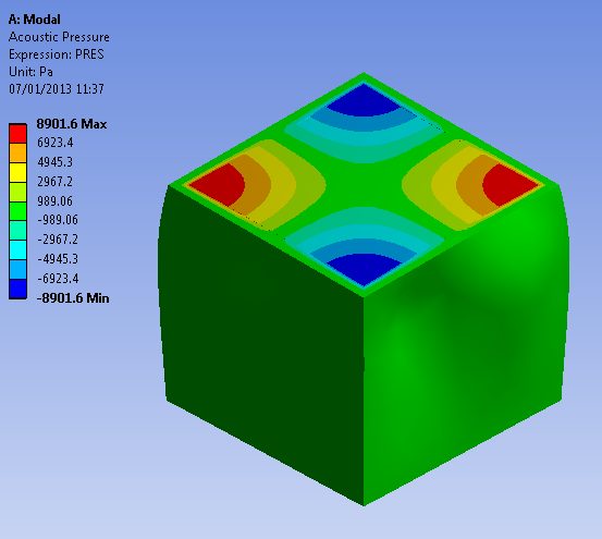
In today’s marketplace companies are using simulation technology more and more in their product development process to make product development faster and to produce better quality products. Often the assessment of the acoustic qualities of a product is conducted towards the end of the design cycle in a build and test scenario which is both costly and time consuming. If you want to produce quieter products, faster, then simulating acoustics with computer aided engineering (CAE) tools can help you get there. Understanding the acoustic properties of the design is key to producing the best possible outcome and with today’s CAE tools this is not just possible but is easier and faster than ever before. Typical Applications of acoustics include: Sonar Design of concert halls for…
Topological Optimisation with FEA
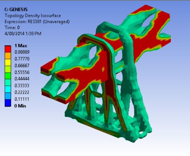
Often companies are under huge pressure to minimise the cost and weight of their products and optimise their design. Finite element technology allows engineers to improve their design in a virtual simulation world but often this is done manually using a trial and error approach. By using the optimisation kernel inside ANSYS (powered by GENESIS, developed by VR&D) this design process can be carried out much more quickly and easily. Optimisation methods in finite elements are either based on optimising grid locations (shape optimisation), geometric properties (sizing optimisation) or material properties (material optimisation). A special case of shape optimisation, where grid points can only move in normal (or a given) direction to the shell is called topography optimisation. A special case of material optimisation…
Simulation Driving the Transport Industry
LEAP Australia recently ran a webinar demonstrating some of the processes and factors to consider when embarking on the simulation driven design process. Watch the recording below: Earlier this year, Melbourne hosted the 2014 International Truck, Trailer & Equipment Show (ITTES) and – amidst declining automotive, mining and manufacturing industries in Australia – the event posted a fourth consecutive attendance record. The transport industry, like many other Australian industries has not been spared from the global economic downturn. However, Australia is a population scattered over an expansive continent that is reliant on the transport industry to convey and deliver the basic living essentials. Australia is also deeply immersed in a growing digital e-commerce lifestyle supported by efficient order-tracking systems, and a road-transport infrastructure that –…
An Overview of Methods for Modelling Bolts in ANSYS
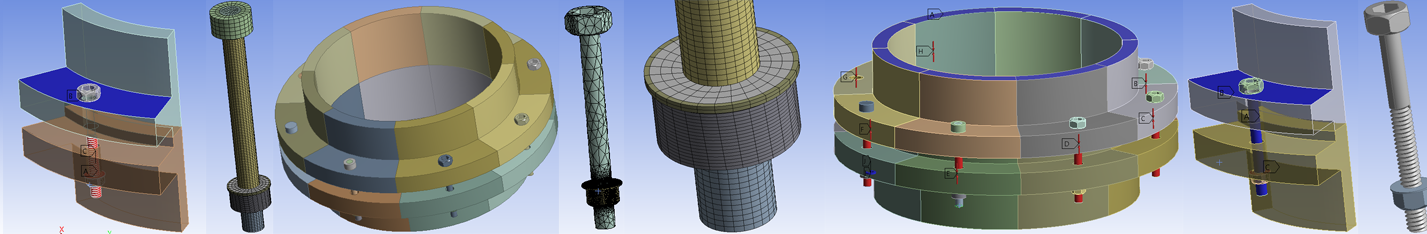
Bolted joints are commonly used to assemble mechanical structures. Modelling bolts for three-dimensional finite element applications has always been a tricky proposition because the details of bolt geometric features usually result in large model size and high computational cost. Therefore, efficient methods to model bolts are always desirable. The approach to modelling bolts usually involves undertaking the following: Prepare geometry: bolt and associated components Mesh: Minimum DOF for best representation/ Hex or Tet Contact: load transfer/stress Load definition: – Step 1: Apply bolt pretension load – Step 2: Lock the defined bolt pretension load – Step 3: Apply in-service loads to structures How one prepares the bolt geometry is an essential factor that will influence the subsequent modelling techniques including meshing, contact and analysis…
Non-linear FEA: Contact Stabilisation

When it comes to discussing non-linear capabilities, non-convergence error messages are the most common stumbling block. A non-linearity, in other terms, a change in the stiffness matrix as the calculation is performed, can be due to yielding (plasticity), deformation of the structure (eg. tension on a fishing rod) or to a contact status change. When using an implicit scheme it is generally not possible to predict beforehand where the stiffness of the structure is heading, so extra care should be taken when setting up the model. Focusing on contact, one of the main difficulties encountered when performing non-linear analyses is in detecting a change in status of the contact. In the finite element model the contact definitions are treated as springs which…
Meshing Improvements with ANSYS 15
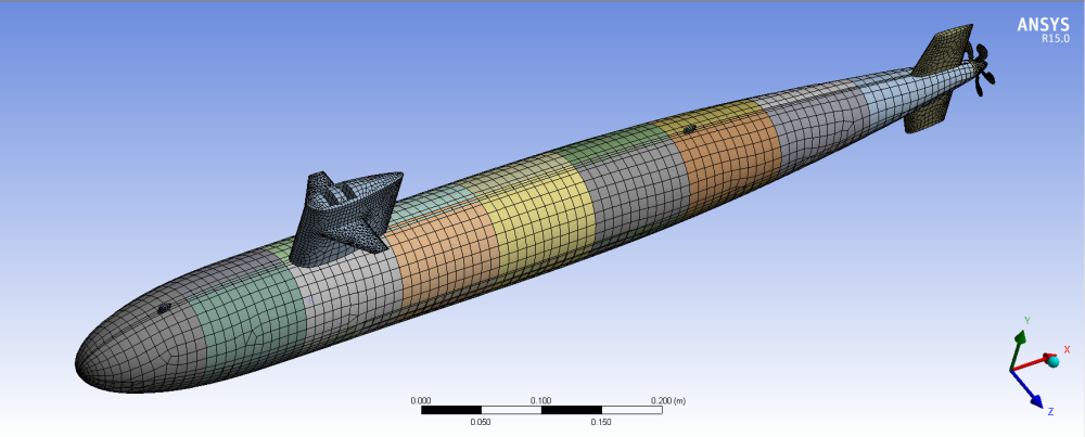
ANSYS Meshing has developed rapidly within the last five years; Body by Body meshing was introduced in 2011 with the emergence of R13, followed a year later by Mesh Connections in R14. A little known feature within R14 is the capability to record and replay meshing strategies in order to increase meshing robustness (See image below). A new feature within ANSYS R15 is the introduction of parallel part meshing, where ANSYS Meshing will use one core per part within an assembly. The increased speed of mesh generation in R15 compared to R14.5 is very noticeable, with meshing times reduced by at least half for almost every model tested. The great part about this new feature is that it…
What is Fatigue?
Fatigue is failure under repeated or otherwise varying load which never reaches a level sufficient to cause failure in a single application. Component seems to lose strength after multiple load applications, appears to get tired, hence the name “fatigue”. Failure caused by fatigue can be minor or catastrophic. The consequences of failure are often very costly and it is estimated that 80-90% of all structural failures are caused by fatigue. Catastrophic failure by fatigue often occurs without warning at low stress levels (see Figure 1, 2 and 3). A paper clip that is straightened and then bent back and forth in the same spot about five times will fail and break into two pieces. That is an example of a low cycle…