
LEAP Australia recently ran a webinar demonstrating some of the processes and factors to consider when embarking on the simulation driven design process. Watch the recording below:
Earlier this year, Melbourne hosted the 2014 International Truck, Trailer & Equipment Show (ITTES) and – amidst declining automotive, mining and manufacturing industries in Australia – the event posted a fourth consecutive attendance record.
The transport industry, like many other Australian industries has not been spared from the global economic downturn. However, Australia is a population scattered over an expansive continent that is reliant on the transport industry to convey and deliver the basic living essentials. Australia is also deeply immersed in a growing digital e-commerce lifestyle supported by efficient order-tracking systems, and a road-transport infrastructure that – until more recent times – had no real urgency to be innovative.
3D CAD Model of a semi-trailer
The humble semi-trailer – responsible for the safe transport of your precious ebay items – is a typical example of a structure that has probably not evolved too much over the decades, with natural progression quickly eliminating the products that failed to meet the old ‘built to last’ adage. Nowadays, companies understand that ‘built to last’ generally equates to over-engineered, expensive or uncompetitive. The traditional semi-trailer not only has to meet durability and reliability requirements, but – in today’s competitive market – weight-reduction, reduced fuel-consumption, ease-of-manufacture, ease-of-repair/inspection, and increase in deliverable payload have rapidly become key design considerations. Optimising the traditional semi-trailer design to address all this criteria can be a reasonably trivial task through the use of Finite Element Analysis (FEA).
FEA software tools – such as ANSYS – can easily interface with your existing 3D CAD geometry to quickly prepare, set-up, solve and visualise your simulation results. An intuitive, easy-to-use graphical user interface and highly-automated workflows result in the rapid uptake by engineers and designers.

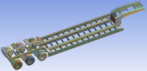
Finite element model of a semi-trailer frame
Simulation products like ANSYS are now widely used in commercial applications – alongside 3D CAD systems – as mainstream design tools. ANSYS Inc. continue to pioneer this technology and the ideology of Simulation Driven Product Development (SDPD) that encourages the use of FE simulation to explore concepts at the early stages of the design process. A validated conceptual design can significantly minimise problems downstream during the detail, prototyping, testing and production stages of the product development process.
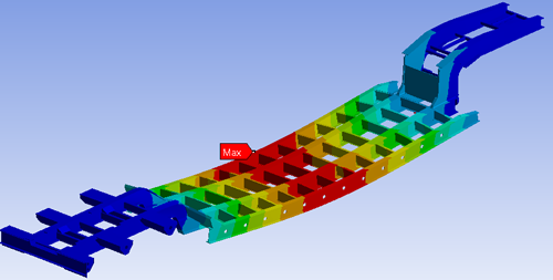
FEA Deformation plot of a semi-trailer frame under load
SDPD is only possible when the following key FEA requirements are satisfied:
Speed
The conceptual design process is driven by exploring as many different designs as possible to arrive at the best concept – or eliminate the worst designs – as quickly as possible.
The FE Solver speed is critical – faster simulations mean more design iterations. There are a number of different solvers available, such as direct sparse, PCG, JCG, AMG, etc. that can offer computational efficiency gains depending on the application and physics involved. Most of the time we won’t have to worry about which one to use as some FEA codes will automatically select the appropriate solver to use.
Advanced computing capabilities such as the ability to distribute the solver across multiple CPUs (Central Processing Units) can significantly improve solve times, and in some cases provide a linear increase in speed, that is, solving on 4 CPUs can reduce solve times to ¼ when compared to solving on 1 CPU. The advancement of GPU technology (Graphics Processing Units), which utilise ‘000s of cores, are now proving to be the next generation of processing technology architecture.
Parametric Design Optimisation Capability
All mainstream 3D CAD systems are based on parametric technology and workflows, as originally pioneered by PTC Pro-Engineer (Parametric Technology Corporation) and its latest successor in PTC Creo. Parametric technology enables engineers and designers to incorporate design-intent into their 3D models and easily modify geometry by changing dimensions.
Some FEA tools, such as ANSYS, are parametric and can even take advantage of the same parameters in CAD, to perform ‘what-if’ simulations. What if I change the thickness of my RHS section from 6mm to 4mm? How will that impact the stresses in my trailer frame? Will it sag under load? How much life can I expect before fatigue cracking becomes an issue? Parametric functionality is at the core of SDPD.
In fact, parametric technology can actually turn design optimisation into quite a trivial task. The ability to tag both input design parameters (e.g. dimensions, material properties, etc.) as well as output simulation parameters (e.g. maximum stress, resultant mass, minimum bolt pre-tension, etc) creates the basis for closed-loop simulations. Goal-seeking functionality can be easily performed and the FEA software will automatically do all the hard work for you. Example:– Reduce the maximum stress in the trailer to 100MPa by varying the RHS thickness range between 2mm to 8mm, and change weld sizes accordingly – then let the software do the rest.
CAD Integration
3D CAD geometry is the foundation for most FEA simulations. The ability to perform geometry changes and automatically update your FEA setup for consequent design iterations is paramount.

FEA stress plot of a welded sub-model section highlighting high stress hot spots
Automotive companies in Australia have been utilising SDPD for decades to push the boundaries of innovation and now it seems the heavy transport industry is catching up. Driven by pressure to reduce weight, increase payload and decrease time to market, trailer manufacturers are discovering the advantages of SDPD. Cost savings derived from a reduction in materials and more efficient manufacturing processes (e.g. decreasing the number of welds) is just the beginning. When one considers the continuing strength and inherent competition within the Australian heavy transport industry as evidenced by the strong showing at this year’s ITTES, the need to bring to market the strongest, lightest and most efficient products possible becomes increasingly important.
The transport industry in South Africa faces similar challenges to that of Australia – distances are vast and a strong mining industry demands high payloads and robust vehicles. South African company Alutip utilised SDPD early in their design process, managing to shave off a quarter of the material from their original tipper design while retaining the required strength and load capacity. This kind of innovation – achieved through SDPD – is increasingly being adopted by companies locally as a renaissance of sorts takes place in an industry that is transitioning from a mentality of “if it ain’t broke” to a deep clear understanding of their product’s performance.
For more information on Simulation Driven Product Development, contact LEAP Australia.