The inverted pendulum on a cart is a classic control theory problem for demonstrating control of an inherently unstable system. Left to its own devices, an inverted pendulum will always fall away from the centre. The cart is controllable however and can move either left or right in order to stabilise the motion of the pendulum and keep it balanced in the centre. There are many examples of this type of system in engineering from balancing rockets using gimbals to balancing a human being on a Segway.
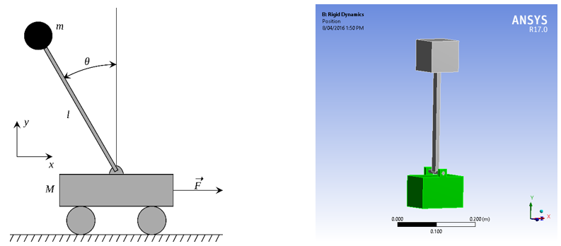
The simplified pendulum model consists of a cart with mass M and propelled by a force F in addition to a mass m at the end of a rod. The carts motion is restricted to only moving in the x direction and is assumed to be frictionless (although not required to be). The control system drives the force on the cart in relation to its two targets. The primary goal is to balance the pendulum on top of the cart and the secondary goal is to maintain the position of the cart at x=0. These goals strongly compete with each other so cannot be considered in isolation (an important consideration which we will touch on again later).
First the differential equation form of the system is derived for small changes in the pendulums position and linearized around Θ≈0:

Deriving a transfer function for this system produces a somewhat unwieldy pair of transfer functions in their general state so the measured variables from the Mechanical model have been substituted and the answer simplified:

This gives us a mathematical description of the system which we can use to predict performance. There is a single input (force) and two outputs (pendulum angle and cart position) that we want to control. This leads us to design a control system with at least two input measurements and one control output. It is possible to design a MISO (Multiple-in Single-Out) or MIMO (Multiple-in Multiple-out) controller based on a PID loop configuration but it usually relies on the systems outputs and inputs being loosely coupled or not coupled at all. In this case both of the outputs are reasonably tightly coupled so any change at the input of the system has a large impact on both of the outputs very quickly. So we need a more advanced control loop.
In the same way that Classical Physics (based on Newton’s Laws) can be considered a subset of Relativistic Physics (i.e. replace certain constants with zero and the equations become the same), Proportional-Integral-Derivative Control can be considered a subset of State-Space Control. If we were to attempt to control this system with a PID controller, it’s likely that angle of the pendulum would be chosen as the measurement. The University of Michigan has an excellent page on the difficulties associated with this configuration but in essence, while the PID controller can stabilise the pendulum angle successfully, the cart usually ends up shooting across the domain in the horizontal direction (or oscillating wildly if poorly tuned).
A State-Space controller is an expansion on the idea of a PID controller which allows the controller to use more information about the system in its calculations. For example, in this system, we have access to the angle, angular velocity and angular acceleration of the pendulum, as well as the position, velocity and acceleration of the cart. Referring to the differential equations noted previously, this happens to match all of the variables which implies we can control the system more strongly if we use more than just the displacement to control the force.
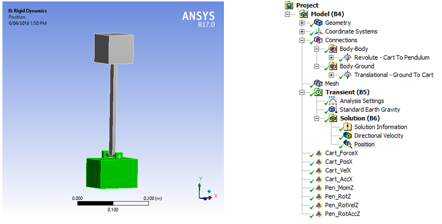
Here is the summary of the model in ANSYS Mechanical:

Figure 2 – Mechanical Model and associated configuration
There is a single revolute joint between the pendulum and the cart. A translational joint is used between the cart and the ground reference. The control system is going to be designed and simulated in ANSYS Simplorer so pins are created to expose the various important inputs and outputs from Mechanical (these can be found at the bottom of the tree). There is a single input (Cart_ForceX) and the rest of the pins are outputs from each of the joints.
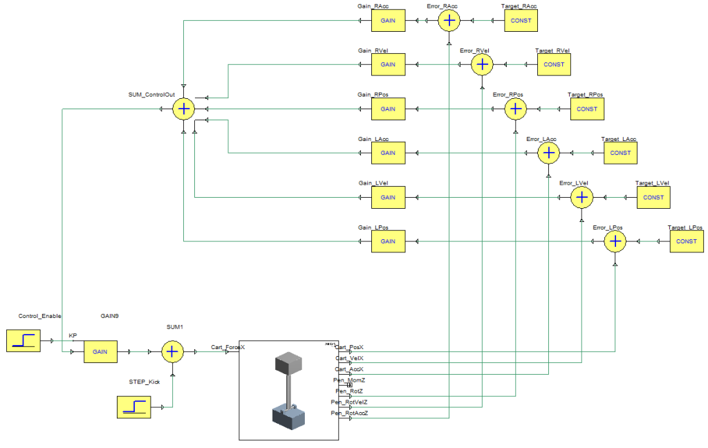
In Simplorer, we load the Mechanical model as a Rigid Body Dynamics Co-simulation sub-circuit. Since there is little requirement for precise positioning in the x direction, any extra integral control on the position will be neglected and only proportional gains will be included for each of the model outputs (linear and rotational position, velocity and acceleration). Alternatively, we could have mathematically generated an S-domain or Z-domain transfer function to model the controller and replaced the schematic below with a single block (this is particularly useful for testing state-space observer functions). See the image below for the Simplorer schematic.

Figure 3 – Simplorer Schematic of the ANSYS Mechanical model and the State-Space controller
Two additional blocks are included at the bottom left. These are present to give the pendulum a small kick to push it away from the stable point and also to disable the control system from catching the pendulum immediately. The control system is disabled for the first 0.7 seconds before it is allowed to apply force to the cart.
Variables are used to parameterise the control system and a range of parameter values are simulated to roughly tune the system. After running 256 different simulations (roughly 25 minutes on a quad-core laptop), the following control values were chosen:
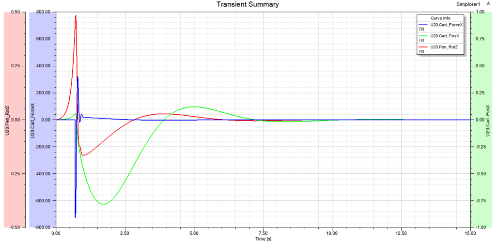
 The angle of the pendulum has the strongest effect on the control force with the rotational velocity and linear parameters having the least effect. Simplorer tracks all of the measurements and control values in the system and they can be plotted during and after the simulation for diagnosis and performance evaluation. Below is a summary of the model transient simulation:

Figure 4 – Performance Summary of Pendulum State-Space Control System
Simplorer also generates a simulation summary file which allows us to load the transient results into Mechanical for further post-processing (animation below at half real-time speed).
Further stages in this analysis could be the design and optimisation of a state-space observer to calculate any outputs which we don’t have access to since in a real design we may have to limit the number or positions of some sensors. The combination of ANSYS Mechanical and ANSYS Simplorer allows a wide array of control strategies to be implemented and optimised in a virtual system.
| Jonathon McMullan | Brian Graybill |
| ANSYS Applications Engineer (Electromagnetics and Systems) | ANSYS Applications Engineer (CFD and Mechanical) |


