
Lasers are used extensively in the fields of engineering and science, with applications ranging from telecommunications systems, sensing (LIDAR, surface plasmon resonance, scattering detectors), medical technology (optical coherence tomography, ablation), and laser machining (cutting, engraving, welding). Lasers fundamentally emit Gaussian beams, with irradiance profiles that follow Gaussian distributions, as illustrated in Figure 1.

Figure 1 – 2D Gaussian beam irradiance profile
Gaussian irradiance distributions are suitable for many laser applications, but occasionally other distributions – specifically tophat (flat) distributions – are desired. Several methods exist to transform a Gaussian profile to a tophat profile, including beam truncation (using apertures), refractive field mapping (using aspherical lens pairs), and diffractive field mapping (using diffractive elements) [Laser Beam Shaping Overview | Edmund Optics].
Project Outline
Laser machining typically requires tophat irradiance profiles to achieve uniform energy distributions for uniform material cutting, engraving, and welding. The goal of this project is to design a laser cutting head for a 50W/1060 nm semiconductor laser. To reduce the height of the system, a fold mirror will be used to steer the beam vertically from its horizontal origin. The high input laser power requires full STOP (structural, thermal, and optical performance) analysis to compensate for thermal and structural deviations.
Refractive Field Mapper Design
Refractive field mapping involves redistributing the Gaussian irradiance and phase profiles to tophat profiles. This is typically done using pairs of aspherical lenses; the first aspherical lens is used to generate the tophat profile, and the second aspherical lens is then used to collimate the beam. The method outlined in [How to design a Gaussian to Top Hat beam shaper – Knowledgebase (zemax.com)] is used for the beam transformation, where the input Gaussian and output tophat beam parameters are shown in Figure 2.
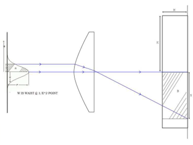
Figure 2 – Input Gaussian beam (left) and output tophat beam (right)
In Figure 2, the input Gaussian beam has beam waist W and the output tophat beam has beam radius K. The tophat radial distance S for a given Gaussian radial distance X to perform this transformation is given in Equation 1.
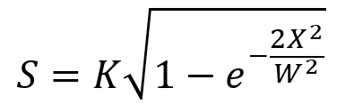
Equation 1 – Gaussian-tophat beam transformation equation
The optimiser uses this transformation to calculate the ideal value of S for a given value of X and compares this with what the simulation predicts. A design with a high quality tophat distribution will have a very small average error between the ideal value of S and the actual value.
Optical Modelling Using Ansys Zemax OpticStudio
A sequential ray tracing solver is the most efficient choice for the accurate simulation of ray distributions in the system, hence Ansys Zemax OpticStudio is used for the optical design. The input Gaussian beam originates horizontally relative to the cutting bed. Aspherical lens pairs are used to perform the transformation, and a fold mirror is used to redirect the beam vertically. This system is shown in Figure 3, where the input Gaussian irradiance and output tophat irradiance profiles are apparent from the ray distributions.
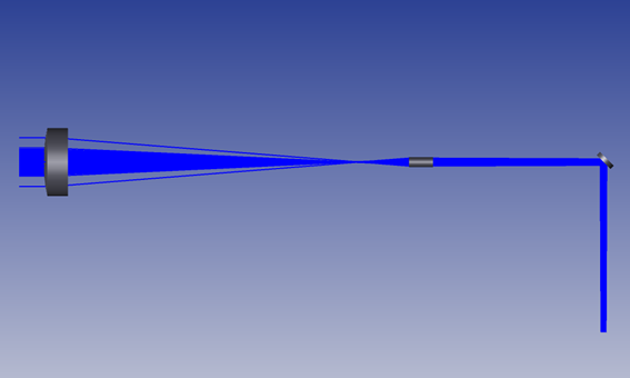
Figure 3 – Gaussian-tophat refractive field mapper design
The initial beam is defined with a wavelength of 1060nm and a Gaussian apodization to achieve an input beam waist of 2.5mm. This input Gaussian profile is shown in Figure 4.
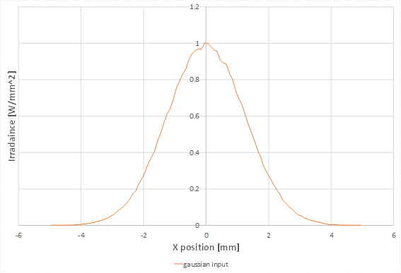
Figure 4 – Input Gaussian beam with W=2.5mm
For this optimisation, the radii of curvature, conic constant, and 4th-6th order aspherical lens terms of both aspherical lenses are varied. The normalised target tophat profile with 0.5mm radius is shown in Figure 5. Following optimisation, a merit function value of 5×10⁻⁵ is achieved, indicating this design produces a good quality tophat distribution with the desired beam radius.
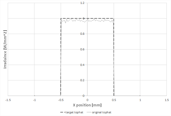
Figure 5 – Target and optimised output beam profile over 0.5mm beam radius
To perform STOP analysis on the system, the irradiance profiles on each lens are extracted, accounting for the internal transmittance of N-BK7 glass at 1060nm. These profiles are then used to generate the temperature and structural changes of the optomechanical design due to the 50W laser source.
Structural and Thermal Analysis
The optical housing is designed using aluminum. Each lens is mounted onto a two-sided retaining ring, which is threaded into the lens tube. The optomechanical assembly – illustrated in Figure 6 – is then mounted onto the laser cutting bed using the front, mid, and back faces as mounting points.
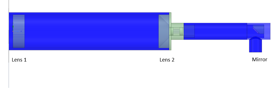
Figure 6 – Optomechanical assembly of refractive field mapper
High optical power levels can heat even very efficient optical systems to the point where performance is degraded. With this system, the primary point of concern is whether the cooling for the second optical element will be sufficient to prevent distortion in the surfaces due to either the chassis expanding or the element itself.
Each optical element has a different loss profile depending on the beam profile. The beam profile is calculated as a part of the ray tracing simulation, after which it is imported into the thermal simulation as an external load. The total loss on each element is similar, but the volume of the second element is 46x smaller by volume than the first element which in turn, increases the loss density by 28x; the total loss of each optical component is shown in Table 1.
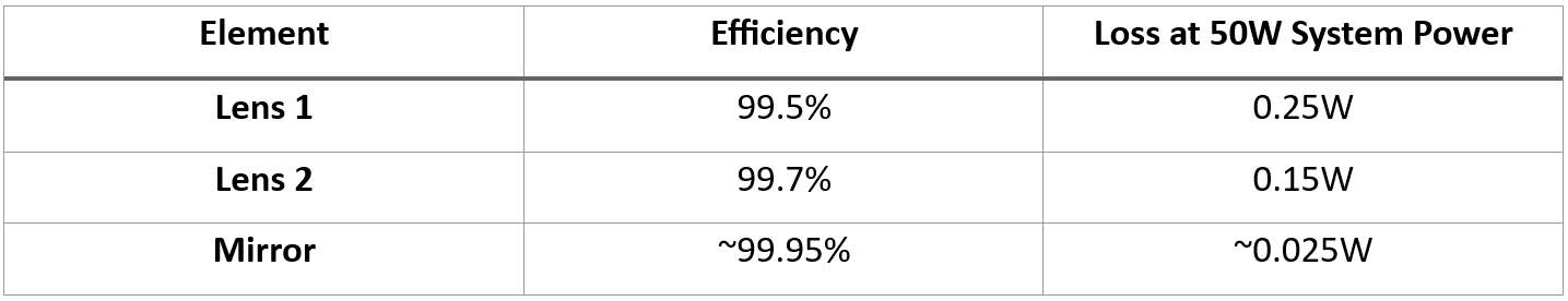
Table 1 – Optical Losses by Element
With the cooling requirements being so much higher for the second element, the coolant loop used for the rest of the system is connected to the area around the second element for additional cooling. The rest of the chassis is cooled by natural convection. The steady-state temperature profile of the optomechanical assembly is shown in Figure 7.
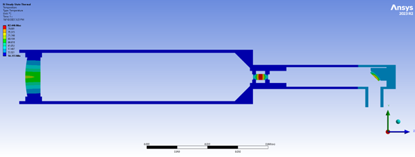
Figure 7 – Thermal Distribution of Optical and Mechanical Components with cooling system
In addition to the change in refractive index due to the temperature change, the shape and positioning of the elements can also be deformed due to changes in the structure. Thermal expansion due to the optical power absorbed by the system in addition to any changes in ambient temperature will cause the surfaces of the elements to distort. This also causes the chassis to expand and misalign the elements.
The cooling system for the second element and the mounting system for the mirror require the chassis to be locked in place at these points. The first element has a cylindrical mount which allows a small amount of expansion along the axis but no expansion in either radial or lateral directions. The temperature is mapped from the previous thermal analysis to the structural analysis as the structural load, shown in Figure 8.
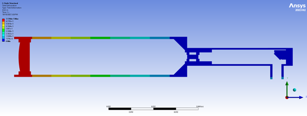
Figure 8 – Structural Deformation of Optical and Mechanical Components
STOP Analysis
Interpreting the change in optical performance using the mechanical postprocessing is very difficult at best, impossible at worst. The STAR module in Ansys Zemax OpticStudio can import both structural and thermal data from a mechanical simulation and postprocess it into separate thermal, surface deformation, and rigid body motion to isolate specific areas where the design can be improved. Further information can be found in the Ansys Zemax OpticStudio help material (OpticStudio STAR Module: Ansys Data Export Extension – Knowledgebase (zemax.com)). The thermal, surface deformation, and RBM result of the STAR import of the first aspherical lens is shown in Figure 9.
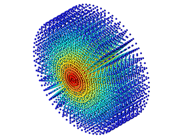
Figure 9 STAR data import result of thermal, surface deformation, and RBM of first aspherical lens
The thermal, surface structural, and RBM FEA datasets are imported into the STAR module, and the system is re-run and updated to evaluate their impact on the system performance. The individual contribution of each of these on performance – gauged using the merit function – is shown in Table 2.
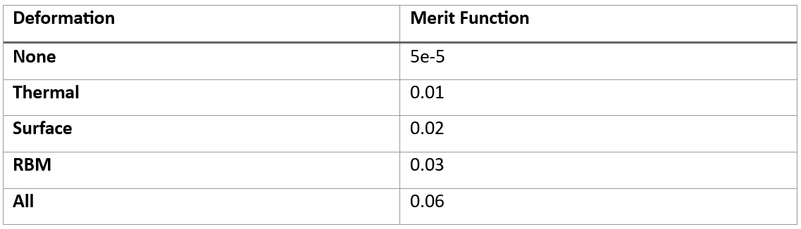
Table 2 – Contributions of thermal and structural data on system performance.
The resulting merit function increases from 1e-5 (initial performance) to 0.06, indicating a substantial performance degradation. The rigid body motion of the lenses contributes half of the total degradation in performance. Analysis of the output beam reveals that it no longer follows a tophat distribution – instead showing edge ringing – due to thermal and structural effects. The resulting output beam profile is shown in Figure 10.
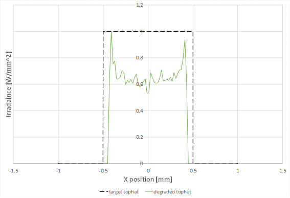
Figure 10 – Beam profile showing degradation of output tophat profile due to thermal and structural effects
The optical system is then re-optimized with the thermal, surface, and RBM FEA datasets included. The same merit function is used to generate the tophat profile and re-collimate the final beam.
Following re-optimisation, the merit function is reduced from 0.06 to 0.003, indicating a 20x improvement in system performance. The resulting output beam profile is shown in Figure 11, showing the restoration of the tophat profile, although it is noisy relative to the original profile – this is expected when FEA data is included in the analysis.
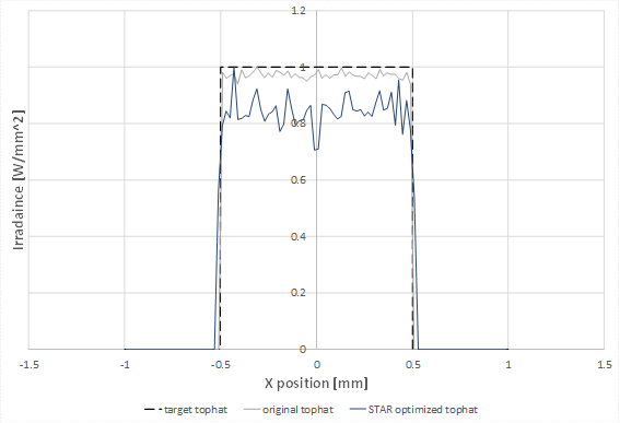
Figure 11 – Optimisation with thermal and structural effects included, showing restoration of the tophat beam profile
Here we have seen how simulation with Zemax OpticStudio has helped us arrive at an optomechanical design that will generate the required collimated tophat output beam for the laser cutter and will remain robust under the expected thermal and structural deformations caused by the laser source.
If you have a similar Optomechanical design problem, feel free to get in touch with the team at LEAP Australia to help you get started with the right simulation tools for your specific needs.