
Monash Motorsport is a student-run team who compete in the largest Engineering Design Competition in the world, Formula SAE. Students from universities all around the world design, manufacture, test and compete with formula-style race cars.
Competing since 2000, Monash Motorsport has steadily improved in performance on and off the track. The team is comprised of Monash University students from a range of faculties, including engineering, commerce, science, design and law; that work collaboratively in technical, business and management aspects.
Formula Student is divided into distinct classes; Combustion, Driverless and Electric. At competitions, each car competes separately and is judged in two types of events, Dynamic and Static. Static events allow the team to demonstrate their knowledge behind the development of the cars and test industry skills such as entrepreneurialism, financial acumen and the holistic engineering design process behind the cars. Dynamic events are the culmination of the design process, testing the performance of the cars in a variety of scenarios. These events require more than just the quickest car; they are a test of reliability, efficiency and driver skill.
Following the success of our 2019 cars winning Formula SAE’s Australasian competition, 2020 was an opportunity to review and refine the design of any components that had room for further optimisation and performance extraction before heading to Europe to compete against the world’s best. My name is Cooper Morrison, I’m a 3rd year mechanical engineering student and have been on the team for 2 years. This is a snapshot of my experience designing the new wheel centres for Monash Motorsport’s new race car.
The first stage in the design process for the 2020 iteration of the 13” wheel centres was conducting extensive research, noting that this design had to remain compatible with our M19 vehicles which limited the scope of the redesign. Following a literature review of previously documented MMS designs, academic papers and other teams’ successful approaches, we focused on a subtle redesign of the wheel centre geometry combined with a review of different material options – mainly considering different alloys of aluminium for the high strength to weight ratio.
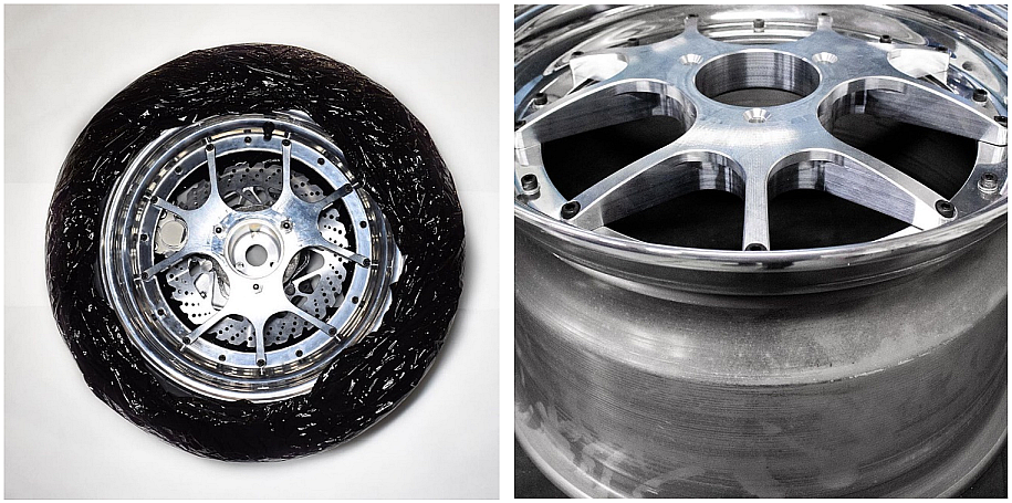
Figure: 2019 Outboard assembly and wheel centre
It was important to establish goals and constraints early in the design process to ensure that time wasn’t wasted fixing simple problems later. Firstly, understanding the relevant rules and ensuring that any design conforms with them, mainly that the wheel may not extend beyond the outside face of the tyre from a top-down view. This constraint is significant as having a larger second moment of area will improve the centres’ performance with lateral stiffness, but this of course requires a compromise with mass that inevitably must increase as the design approaches a certain thickness. This part was designed as part of an update package for the 2019 cars, and so had to integrate fully with the existing parts on the car such as the hub, wheel shells and brake assembly. This limited the possible geometry on the inboard side and around the mounting points, dictating the outer and inner diameter of the design. It was also important to ensure that the custom tools the team uses to lift the car and remove the wheels were compatible with the new wheels, or at least were easily adaptable/ replaceable.
From here I set mass and stiffness targets. The existing 2019 wheel centres were obviously the first point of comparison, setting the minimum performance benchmark to warrant the investment of new wheel centres. The previous designer Lachlan Palmer achieved an individual mass of 906 g and a stiffness of 0.15 deg/g with a 3-axis machined set of Aluminium 2024 T6 wheels. From here, the team’s goals for overall mass reduction lead to the section leaders assigning a target goal of 800 g per centre (saving over 11% mass on wheel centre).
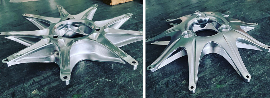
Figure: Completed 2020 wheel centre
After determining the design stress for simulation, factoring in predicted cycles and operating temperature, I began the concept creation and simulation of some of the basic ideas I had encountered or conceived of during my research stage. I began by benchmarking the 2019 design and making alterations to this design to see where mass is most efficiently used when 3-axis machining constraints are ignored. Using this information, I started to try out design ideas, starting initially with adapted designs from previous years and simple core theory designs like using I-beams or spokes with webbing. This stage was important for my personal development to start to understand how mass can be used and what design features were effective, as well as developing CAD & simulation skills along the way. Implementing this rapid design generation strategy in the early concept phase allowed me to come up with multiple solid concepts before moving onto further refinement and optimisation. It was essential to keep track of each concept in an organised manner with a measure for comparison; based on a theoretical points gain or loss calculation of each design at competition. This enabled fast and efficient concept creation, making it easy to analyse several designs and see how they performed in comparison to each other.
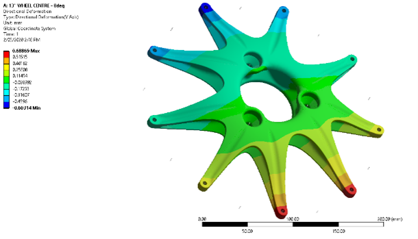

Figure: 2020 wheel centres – ANSYS FEA results – directional deformation
Simulation was critical to this design process, using ANSYS Finite Element Analysis software I was able to model the loads on the wheel centre and use this information to drive decision making. The simulation model was developed in the early stages of the process and borrowed heavily from work done in the years before. Mesh settings aimed to strike a balance between accuracy and solve times to iterate effectively. The model included the hub, centre and wheel shell geometry joined using frictional contacts and springs to model the bolt clamping interaction between the parts. A remote force was applied from the contact patch centroid onto the lips of the shell biased depending on each load case to model the design as closely to real life as possible. Our load cases come from calculating the load transfer from lateral and longitudinal acceleration data from the car’s onboard sensors and solving through the suspension system to determine the maximum forces at each corner of the car.
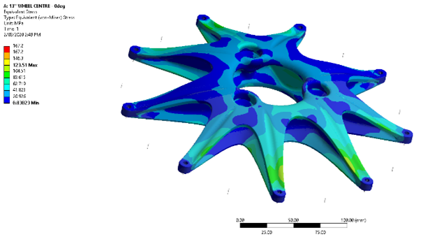
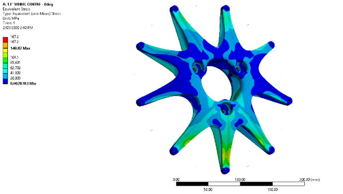
Figure: 2020 wheel centres – ANSYS FEA results – von-Mises stress
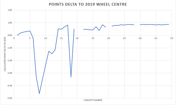
Figure: Performance of 2020 wheel centre concept designs relative to 2019
After finalising my concept generation to a select few designs, I began to consider, in much more detail, the manufacturability of the potential part. For help in this regard, I turned to Andrew from Wirawaji, another long-time sponsor of the team who specialises in machining, who helped account for manufacturing constraints on each potential design so that the final design could be created efficiently with Wirawaji’s 5-axis machining capability.
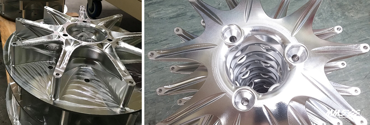
Figure: Machined wheel centres (thanks to Wirawaji)
The result of this process and partnership with valued sponsors such as LEAP produced a wheel centre with a stiffness of 0.12 deg/g and mass of 731g per centre – a mass saving of almost 20%, far exceeding our original goal!
With more time available for this project, I would have also used the ANSYS topology optimisation capabilities to explore more organic design possibilities and utilise some of the freedom in the geometry that 5-axis machining allows for. Topology optimisation is at the forefront of engineering, especially with more prevalent use of 3D printed parts and the human limitations of creativity and CAD skills. I am now looking to use topology optimisation in ANSYS in my current design of a brake rotor and mounting to continue my learning in this area and help continue to optimise these parts of MMS’ next vehicle.