
The introduction of parallel part-by-part meshing to ANSYS Mechanical 15 back in 2013 was revolutionary. Structures which took hours to mesh now wrapped up in minutes, unfortunately removing one of our favourite excuses for taking a tactical nap. One of the limitations to this new feature was the fact that Multibody parts were still meshed in serial. Given that customers in the maritime, aviation and defence industries all utilised Multibody parts to connect shell assemblies, this was a pretty big drawback. Introduced in R16 and refined in R17, ANSYS Inc have introduced a suite of tools focussed on “mesh editing” which work to enhance the workflow associated with meshing and connecting fabricated structures. Over the course of these two releases, a number of new features…
Archives
Topological Optimisation with ANSYS 17.0
Utilising the new FREE topology optimisation ACT-extension, one can explore new innovative ways to reduce mass that were not available before. The DoE (Design of Experiments) approach may not be feasible if the design’s shape is not yet defined, while creating CAD models to capture all the potential design possibilities may be impossible. Now imagine starting with an arbitrary volume and having each element within either turned on or off to create the most optimum shape, taking into consideration the applied loads, boundary conditions, and design constraints (such as, a maximum displacement/stress limit required for the design) to achieve an overall weight reduction. In Shape Optimisation, we have constraints and objectives. Constraints define the optimisation’s bounds, while objectives are essentially the goal of the optimisation problem. In the following example, the imposed loadings on the Bell Crank must…
An Overview of Methods for Modelling Bolts in ANSYS
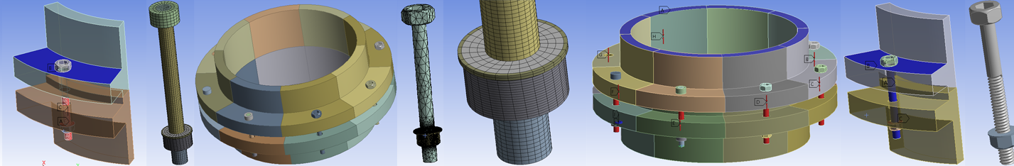
Bolted joints are commonly used to assemble mechanical structures. Modelling bolts for three-dimensional finite element applications has always been a tricky proposition because the details of bolt geometric features usually result in large model size and high computational cost. Therefore, efficient methods to model bolts are always desirable. The approach to modelling bolts usually involves undertaking the following: Prepare geometry: bolt and associated components Mesh: Minimum DOF for best representation/ Hex or Tet Contact: load transfer/stress Load definition: – Step 1: Apply bolt pretension load – Step 2: Lock the defined bolt pretension load – Step 3: Apply in-service loads to structures How one prepares the bolt geometry is an essential factor that will influence the subsequent modelling techniques including meshing, contact and analysis…
Non-linear FEA: Contact Stabilisation

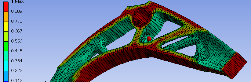
When it comes to discussing non-linear capabilities, non-convergence error messages are the most common stumbling block. A non-linearity, in other terms, a change in the stiffness matrix as the calculation is performed, can be due to yielding (plasticity), deformation of the structure (eg. tension on a fishing rod) or to a contact status change. When using an implicit scheme it is generally not possible to predict beforehand where the stiffness of the structure is heading, so extra care should be taken when setting up the model. Focusing on contact, one of the main difficulties encountered when performing non-linear analyses is in detecting a change in status of the contact. In the finite element model the contact definitions are treated as springs which…
Meshing Improvements with ANSYS 15
ANSYS Meshing has developed rapidly within the last five years; Body by Body meshing was introduced in 2011 with the emergence of R13, followed a year later by Mesh Connections in R14. A little known feature within R14 is the capability to record and replay meshing strategies in order to increase meshing robustness (See image below). A new feature within ANSYS R15 is the introduction of parallel part meshing, where ANSYS Meshing will use one core per part within an assembly. The increased speed of mesh generation in R15 compared to R14.5 is very noticeable, with meshing times reduced by at least half for almost every model tested. The great part about this new feature is that it…