Rocky is a powerful, 3D DEM program that quickly and accurately simulates particle behaviour within bulk materials handling systems used across a variety of industries including mining and minerals processing, food and beverage, pharmaceutical, agricultural and any industry dealing with particulate systems or solids handling applications.
Some keys features include:
- an extensive library of realistic particle shapes,
- an intuitive and easy-to-use interface,
- superior scalability with CPU, GPU and multi-GPU processing,
- advanced breakage and flexible particle models,
- evaluation of belt and surface wear,
- integration with Ansys FEA and CFD,
- complex moving and vibrating boundaries and more.
In this article, we will focus on the integration with Ansys FEA and CFD and provide some examples to demonstrate how this works and why it is needed.
ROCKY DEM as a Component inside Ansys Workbench
For those already using Ansys Workbench, you will be familiar with the ability to drag and drop systems over one another and to share and transfer results from one system to another. The benefit in doing this is share common geometry across multiple systems or to transfer the results from one solver to another allowing multi-physics simulations to be conducted. Rocky’s integration into the Ansys Workbench framework, allows Rocky users to leverage these advantages of Workbench. A user can start with any geometry in Ansys Spaceclaim and share this between ROCKY DEM, Ansys FLUENT and Ansys Mechanical. Furthermore, fluid and boundary forces can solved in Ansys FLUENT and ROCKY DEM, respectively, and transferred to Ansys Mechanical as shown in the example workflow below. Finally, a parametric study can be undertaken with Ansys DesignXplorer or Optislang to conduct a simple ‘what-if’ study or a more thorough Design Optimisation study. Note that Rocky input and output parameters are fully enabled with this workflow.
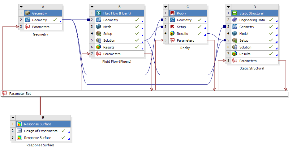
Figure 1: ROCKY DEM as a component system within ANSYS Workbench
DEM-FEA Coupling using ROCKY DEM and Ansys Mechanical
Imagine you’re tasked with designing a bucket conveyor system or bracing support frame for a transfer chute hood. How would you approach such a project?
One way would be to start with a known design, run some hand calculations with some assumptions, and perform a field test. Then in the likely event it fails on the first trial, make design changes based on your best assessment and try again. This physical prototyping approach involves a lot of time, cost, and physical effort, not to mention the potential safety risks associated with any physical testing.
Alternatively, you can use high-fidelity simulation tools like ROCKY DEM and Ansys Mechanical to optimize the process and design parameters in a virtual environment.
How does DEM-FEA coupling work and why use it?
For those using either DEM or FEA technology already, the advantages are clear. DEM allows us to evaluate particle trajectories and bulk flow phenomena and interactions including inter-particle and boundary forces. FEA allows us to determine the impact and severity of these forces on our underlying structure allowing us to troubleshoot systems subject to failure and/or optimise their layout.
By coupling the two simulation techniques, engineers can make less assumptions about loads acting on structures. A typical example is the load acting inside a bin or silo during discharge. With the absence of DEM, the assumption commonly made is to treat the internal load as a hydrostatic pressure which varies with height. Experience has shown that this can lead to an overestimation of the loads, therefore leading to an overly-conservative design.
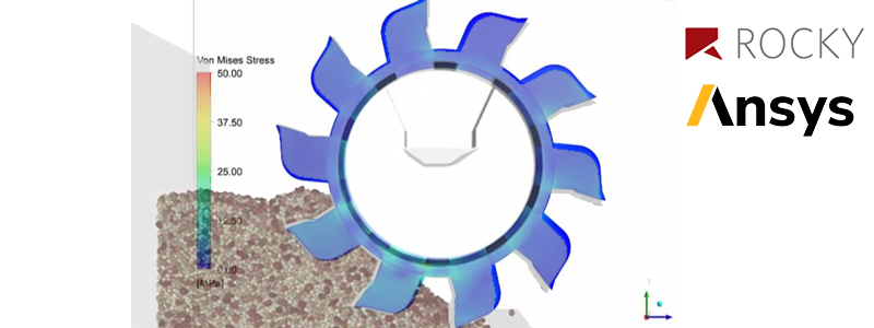
During a simulation, Rocky DEM calculates the loads on each node of the boundary mesh. These loads are then exported as a pressure field for further analysis using Ansys Mechanical, which uses either a profile preserving or force conservative mapping algorithm. This is accomplished via Ansys’ external coupling feature within Ansys Workbench allowing dissimilar meshes to be used for the DEM and FEA models.
Until recently, this was limited to static structural cases for steady-state systems, and has since been extended to accommodate transient applications involving simple or complex motions like a reclaimer or excavator bucket as examples encountered in the mining industry. The example below shows the forces and power required for an excavator bucket to dig through a pile of dirt and the associated deformations and stresses subject to the bucket throughout its digging cycle.
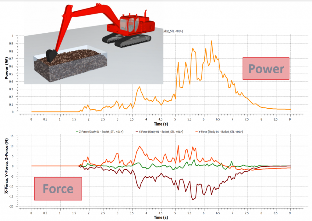
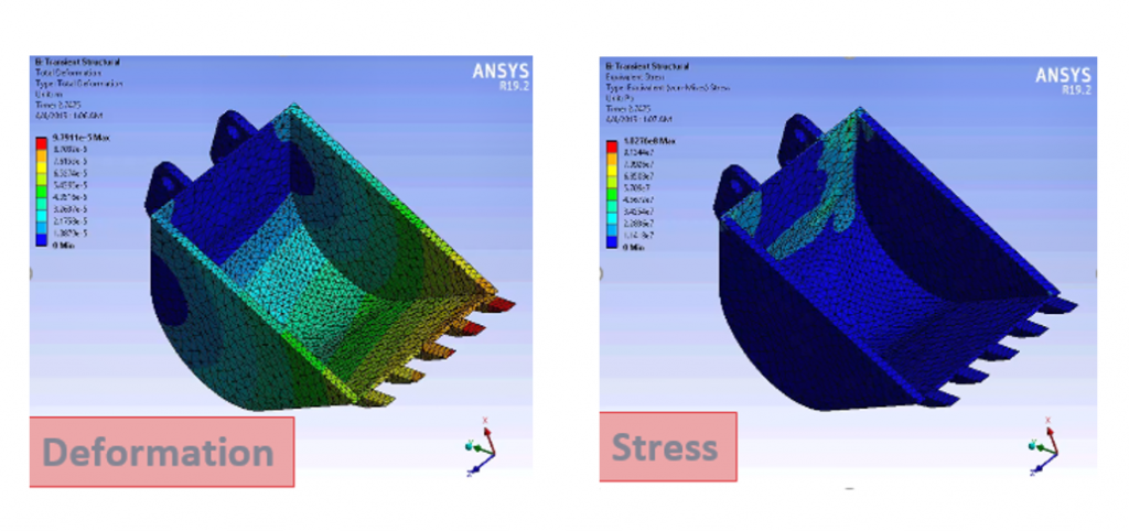
Figure 2: Simulation of an excavator digging cycle using ROCKY DEM-Mechanical coupling
The Benefits of Coupling to ROCKY
The main advantage of the Rocky DEM-ANSYS Mechanical coupled approach is that since particle-particle and particle-boundary interactions are solved and all forces acting on particles are computed on the DEM side, cases in which particles have unique, non-spherical shapes can be accurately solved.
Rocky’s precise shape representation (including custom convex and concave shapes, flexible fibers, and shell particles) combined with its high fidelity contact detection and resultant force calculation, increases the accuracy of the models. By the same token, adhesive/cohesive materials can be modelled using one of the adhesion models available in Rocky DEM.
In addition, as each individual particle is tracked by the DEM solver, the complete history is available for all particles inside the domain (this includes, for example, particle velocities and contact data). Bringing together the extensive post-processing tools available in Rocky, it builds up the level of information that can be extracted from your coupled simulation, providing better insight into your problem. In cases where particles are too small to model individually, ROCKY provides a new ‘coarse-grain’ modelling approach allowing a ‘pseudo’ or scaled-up particle size to be used effectively representing many smaller particles. This has the advantage of reducing computational time without compromising accuracy.
Moreover, Rocky’s dedicated GPU solver and multi-GPU capabilities making it possible to solve large ‘full-scale’ industrial cases with a huge number of particles.
Finally, Rocky features such as adhesion/cohesion modelling, detailed particle collision statistics, energy spectra analysis, and breakage modelling can be simultaneously used with the Mechanical-Rocky coupling solution, broadening the range of cases that can be solved and expanding your analyses to the next level.
For more information or to discuss your application, contact us. Don’t forget to register for our upcoming live webinar on ROCKY and ANSYS Integration