
In the latest release of Ansys SpaceClaim, CAE users can now leverage new scripting capabilities to help efficiently automate the generation of new geometry designs. At LEAP Australia we have been helping customers across Australia & New Zealand to use scripting in SpaceClaim to create design templates that can automatically generate different designs, simply by modifying a few key parameters. Building on the information we shared in our recent webinar and the availability of new features in the latest release 2020R2, these new scripting and feature tracking capabilities in SpaceClaim are now ready for mainstream use.
Ansys’s strength in allowing users to parameterise key design variables is well known. This significantly reduces the need for manual intervention when exposing the client’s designs to various design conditions. Typically during the design phase, multiple geometric parameters are varied whilean initial prototype is developed. Historically, Ansys DesignModeler has helped users to createparametric models but DesignModeler could become unwieldy when working on complex models with multiple dependencies. In contrast, Ansys SpaceClaim has a distinct advantage in working with complex models, but the nature of a Direct Modeller meant that it was not intended to be used to build a model from the ground-up using parameters.
Ansys have addressed this to bring the best of both worlds to SpaceClaim in version 2020 R2 by releasing two powerful new features. The first is the ability to record blocks and the second is to introduce the ability to create scripts using Python API within the SpaceClaim environment. In this blog, we will aim to give you an overview of the first feature called “Block recording” and showcase how this can be leveraged to automate our customer’s workflows.
Recording Blocks in SpaceClaim
The “Record Block” feature in SpaceClaim helps you to modularize your design into various blocks. For example, you can import models with existing parameters. You can also create 2D sketches of lines, arcs, and splines and convert them into 3D models. Block Recording captures all the changes you make to your model in blocks of script. As you perform operations, they are recorded in script blocks. Each block represents a block-of-script that can be used to recreate that part of the model design when the script is run once again.
Using the record blocks feature can help you to develop your designs in a logical and organic manner, helping them improve the efficiency of their CAD modelling workflow. Each “Record Block” feature allows the user to create dimensions within the block operations. Users can create sketches in a block, dimension them, and set these dimensions to be a parameter than can be varied at a later stage. The next section demonstrates how to use the block recording feature to create a parameterized geometry in SpaceClaim.
Geometry creation through Record Blocks feature
In this section, we will look at how to use the block recording feature to create the fluid domain around a piano-key shaped weir. The key steps for creating this geometry through the record blocks feature are illustrated below with the help of a few screen captures.
Open SpaceClaim 2020 R2 and switch on block recording by clicking on the “Blocks” icon. You will see a new panel appear which starts recording these blocks. Once this is switched on, you can switch to the sketching mode to start creating and dimensioning your sketches. Once a dimension is created in a sketch, it can be converted to a parameter.
The sketches thus created can form the building blocks of more complex geometries. Here, a move pattern is created using the sketch created in the previous step.
You can record a custom script written using Python API within the SpaceClaim environment to give you more flexibility in creating your geometries. Result of an operation within a block can create faces, bodies or other geometric entities. These can be selected for subsequent operations as shown in the video below. Upon completion of a block operation, it is often a good idea to change a parameter and rerun the script to ensure it runs without errors.
The next step is to extrude these blocks to form a solid. In order to achieve this, we need to use the pull tool to pull the faces of existing surfaces by the desired distance to create the desired solids. The faces created in the previous pattern operation and from the creation of the custom block can be selected for the extrusion as shown in the video below.
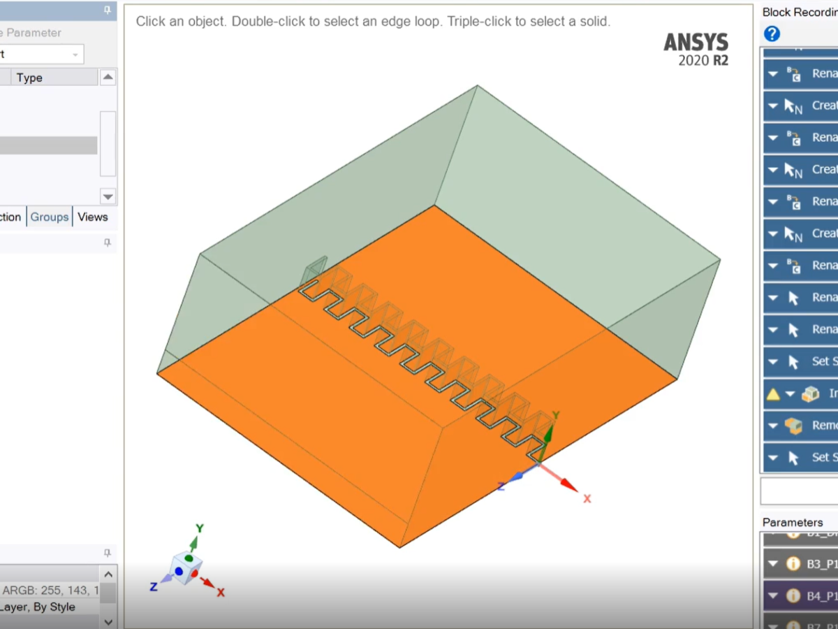
Next step is to create a fluid enclosure around the blocks and specify the necessary boundary conditions as shown in the recording below.
The last step is to use the combine operation to create the desired geometry. This geometry can now be parameterized for the number of keys of the piano weir, and the height, length and thickness of the keys of the weir can also be parametrically varied through this script.
The model is now ready to be meshed in Fluent meshing for running a Volume of Fluid simulation in Fluent. Parameterising the model at the geometry stage can allow us to simulate how the height of the water upstream of the weir changes with the number of keys in the piano weir -but that is a story for another blog post!