
Often companies are under huge pressure to minimise the cost and weight of their products and optimise their design. Finite element technology allows engineers to improve their design in a virtual simulation world but often this is done manually using a trial and error approach. By using the optimisation kernel inside ANSYS (powered by GENESIS, developed by VR&D) this design process can be carried out much more quickly and easily.
Optimisation methods in finite elements are either based on optimising grid locations (shape optimisation), geometric properties (sizing optimisation) or material properties (material optimisation). A special case of shape optimisation, where grid points can only move in normal (or a given) direction to the shell is called topography optimisation. A special case of material optimisation with element material fractions between 0 and 1 is topology optimisation. A special case of sizing optimisation is topometry optimisation, where the thickness of each individual element is a design variable.
All of these options are available in GENESIS, which is a fully integrated finite element analysis and design optimisation software package, written by leading experts in structural optimisation (VR&D). Analysis is based on the finite element method for static, normal modes, direct and modal frequency analysis, random response analysis, heat transfer, and system buckling calculations. Genesis is easy to learn, so no special knowledge of optimisation technology is required.
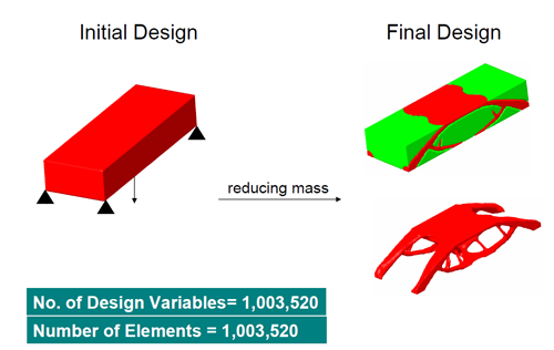
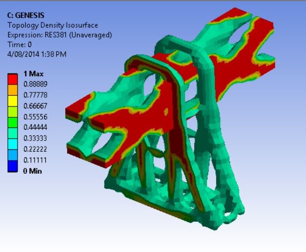
Figure 1: Topology optimisation: optimises the strength of a structure while reducing mass (the elements coloured in red are kept and the green elements are removed)
The benefits of using Genesis optimisation are:
- Reduces Cost and Improves Performance – by generating new designs based on user criteria such as mass minimisation, frequency maximisation, stress or displacement constraints and many more. The automatic process avoids a huge amount of manual design iterations.
- Reduces Engineering Time – Genesis has powerful embedded solvers such as the SMS eigensolver which speeds up solving time and is 2 to 5 times faster for small to midsize problems and 5 to 10 time faster for very large problems.
- Innovative Designs Come To Life – robust designs can be realised as Genesis’ optimiser, BIGDOT, can handle extremely large numbers of design variables. This allows an engineer to explore the entire design space with either topology, topometry, or topography optimisation.
GTAM
GENESIS Topology for ANSYS Mechanical (GTAM) is an integrated extension that adds topology optimisation to the ANSYS environment (as shown in Figure 1 and 2). Topology optimisation is used at the concept level of the design process to create a conceptual design proposal that is then fine-tuned for performance and manufacturability. This replaces time consuming and costly design iterations and hence reduces design development time and overall cost while improving design performance.

Figure 2: An example in ANSYS WorkBench where the GENESIS module GTAM is linked to a Static and linear Buckling Analysis
In simple words: Topology optimisation removes material from a structure while (in most cases) minimising the strain energy (make it as strong as possible). Figure 1 and 3 show simple examples of models with the minimum strain energy as an objective. Other criteria can be used as well (buckling, frequencies etc) both for objectives and constraints. 3D contact can also be included in the analysis.
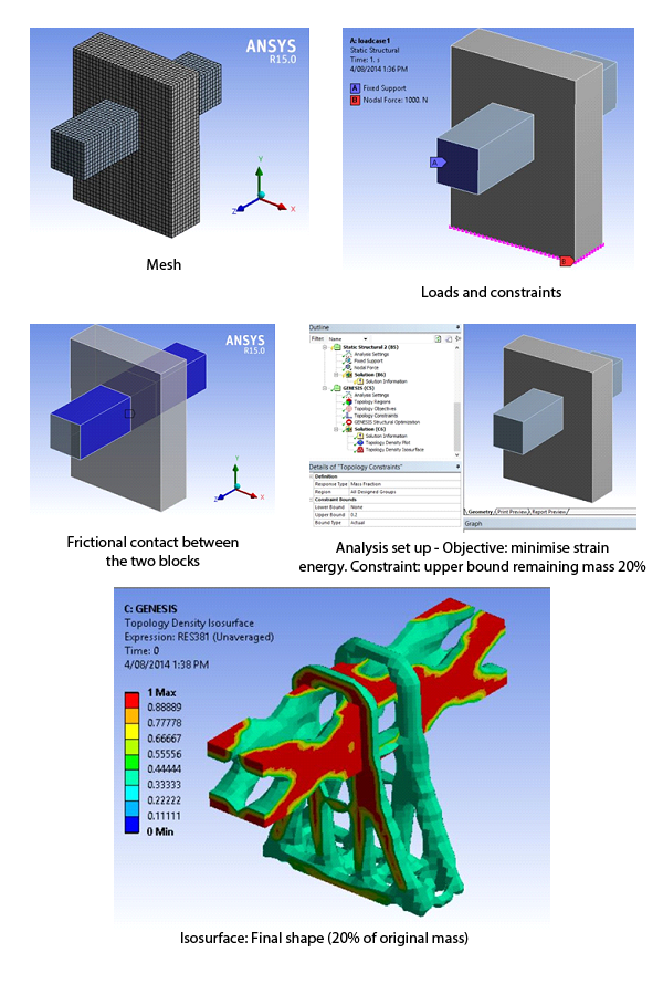
Figure 3: A simple workflow example of GTAM topology optimisation in ANSYS for a model that includes 3D contact
Sometimes the optimum solution may be expensive or infeasible to manufacture. In that case one can use manufacturing constraints in the topology optimisation problem formulation to obtain a practical engineering design as shown in Figure 4 and 5.
As a plugin module within ANSYS, minimal training is required to enable users to quickly apply GTAM to their design process. ANSYS Topology optimisation can be performed for static, normal modes and linear buckling load cases. Optimisation results can be exported in STL or IGES format.
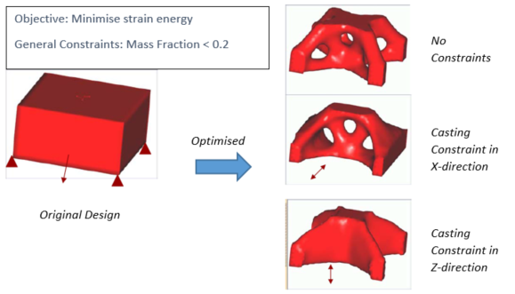
Figure 4: Example of Topology Optimisation with “no constraints” (top right), “casting constraint in x-direction” (middle right) and “casting constraint in z-direction” (bottom right)
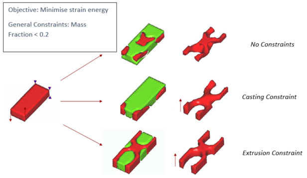
Figure 5: Example of Topology Optimisation with “no constraints” (top right), “casting constraint” (middle right) and “extrusion constraint” (bottom right)
Figures 6~10 show additional examples of topology optimisation in ANSYS Workbench.

Figure 6: Example GTAM – The conceptual design of a car
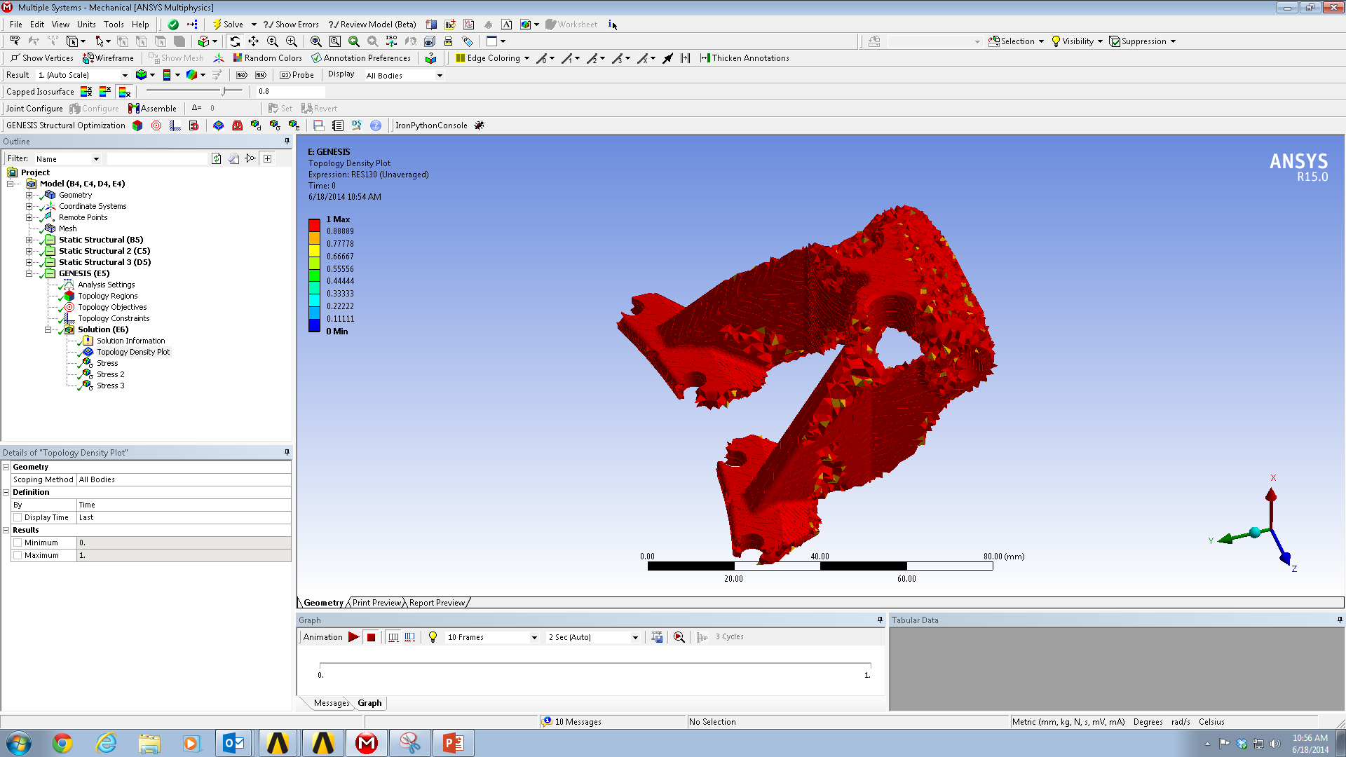
Figure 7: Example GTAM – The conceptual design of an aerospace mounting bracket
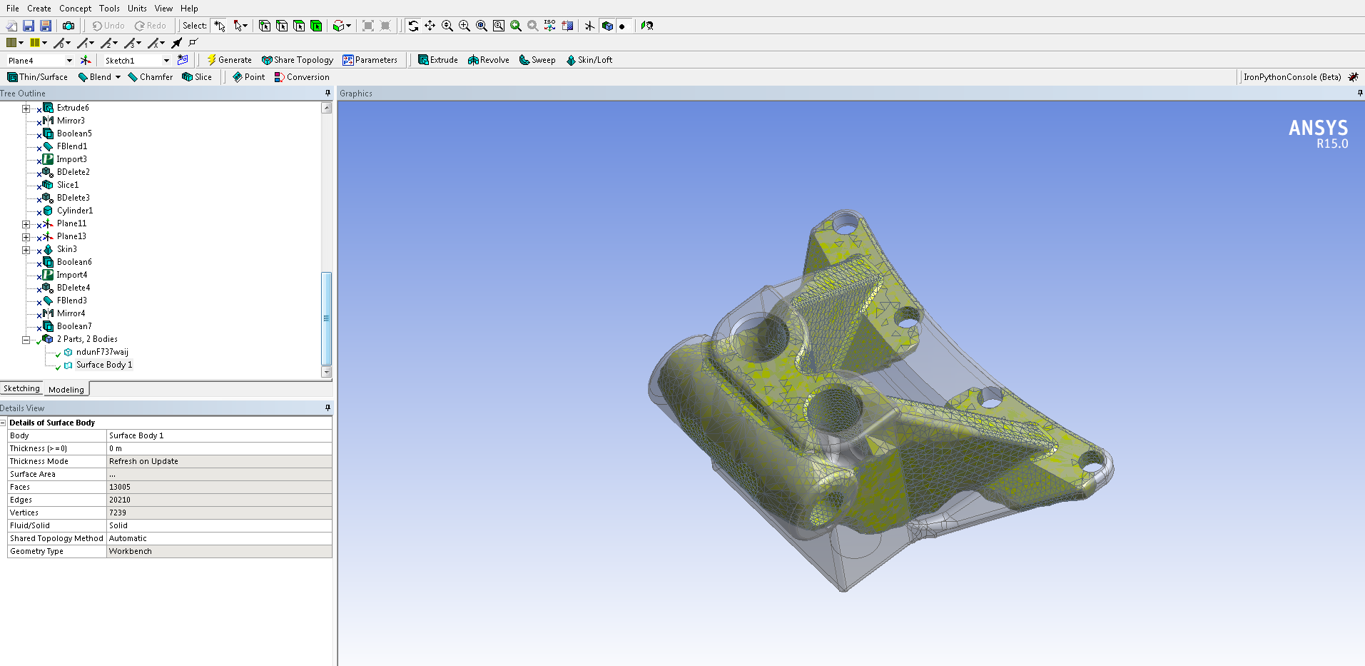
Figure 8: Example GTAM – Export of the optimized shape for the aerospace mounting bracket
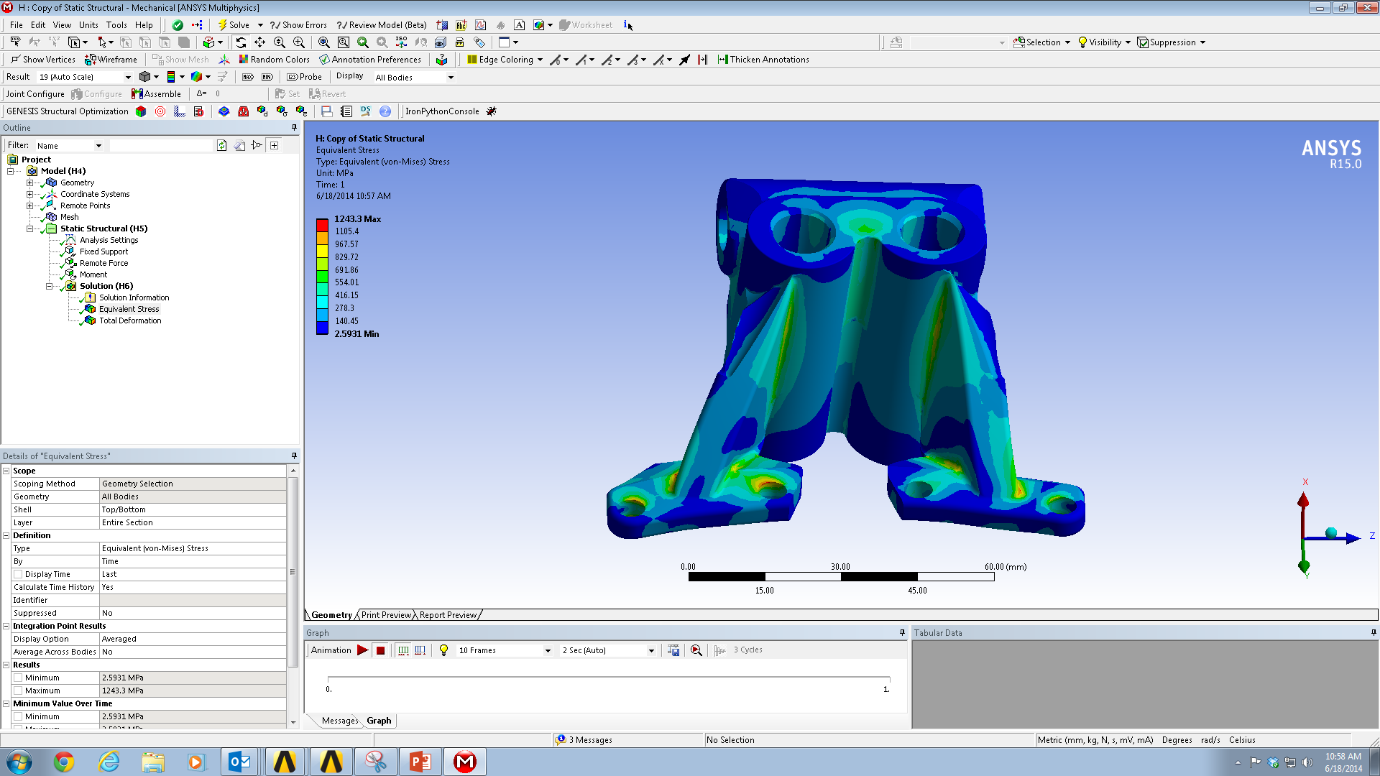
Figure 9: ANSYS – Stress analysis on the optimised shape for the aerospace mounting bracket

Figure 10: The final design of the aerospace mounting bracket
Genesis Design Studio
The standalone version of Genesis (with more capabilities than GTAM) is called Genesis Design Studio. GTAM also offers a direct export option to VR&D Genesis & Design Studio, enabling ANSYS users access to the extended optimisation capabilities, including Sizing, Shape, Topography and Topometry methods:
Sizing Optimisation – is an optimisation capability which allows the user to find the best dimensions of any designable elements like bars, shells and composites (typically per group of elements).
Shape Optimisation – is an optimisation capability which allows the user to find the best shape possible. The software finds the best location of the finite element nodes, which define the shape of the structure.
Topography Optimisation – is an optimisation capability which allows the user to find the location and shape of bead patterns to stiffen panel structures.
Topology Optimisation – is an optimisation capability which allows the user to find the best distribution of material. With topology optimisation, an optimal structure is generated by carving out material from a given design space, allowing for a given amount of material.
Topometry Optimisation – is a unique optimisation capability which allows the user to find the optimal distribution of sizing dimensions over the structure. Like topology, this capability can be used to find the optimal places to take out material. Unlike topology, it also can be used to find the best places to add additional material. Typically the thickness of each element individually is defined as a design variable.
Freeform Optimisation – is a new special shape optimisation capability which allows the user to find the best location and shape of rib patterns that stiffen solid structures. It can also be used to find the best location of grids in any type of structure.
Figure 11 shows an example of a car design where sizing and topometry (which is a special case of sizing optimisation as the thickness of each element in the model is a design variable) are used to increase the first 12 natural frequencies of the model.
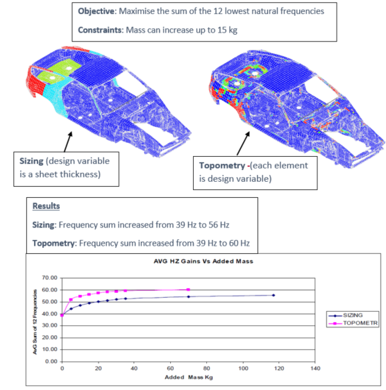
Figure 11: Example of Sizing (left) and Topometry optimisation (right) for car design
Shape optimisation in Genesis requires design variables, shape basis vectors and relationship between the design variables and shape basis vectors. The amount the design variable is changed during optimisation results in a corresponding shape change as shown in Figure 12.

Figure 12: Shape optimisation, grids points are allowed to move and change the shape of a structure along combinations of pre-defined shape vectors
Topography is a special case of shape optimisation where grid points typically move along the normal of a shell element. Topography can be combined with topometry and general shape optimisation as shown in Figure 13.
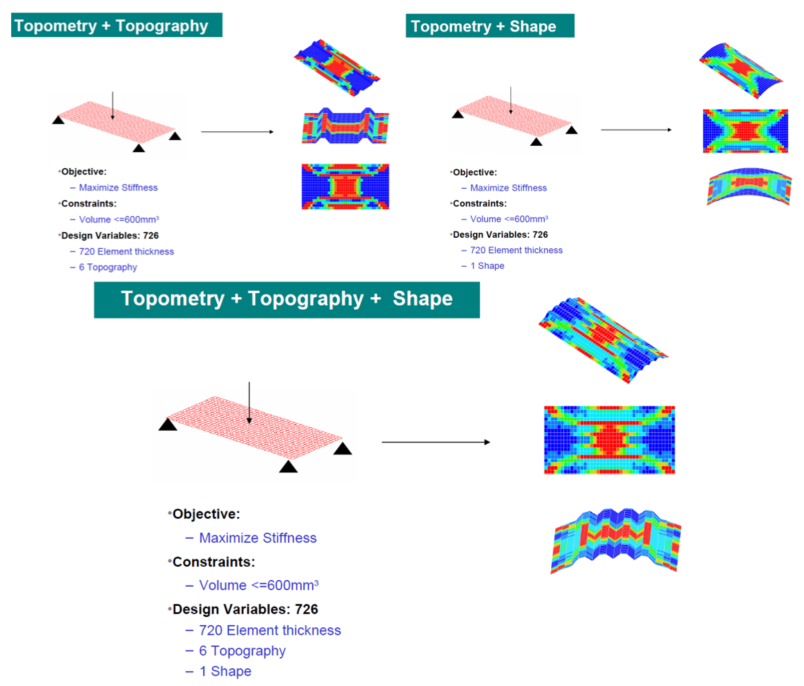
Figure 13: Shape optimisation combined with topometry and topography optimisation
There are similarities between topology and topometry. In topology optimisation the design variables are typically linked to the Young’s modulus and density fraction of each solid element (between 0 and 1) but the volume of the element remains constant, whereas in topometry the design variables are typically linked to the thickness fraction of each shell element, but the material properties remain constant (as shown in Figure 14).
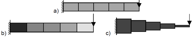
Figure 14: Topology and Topometry – a) Initial design b) Topology: Volume is constant but Young’s modulus is variable c) Topometry: Volume changes as variable but Young’s modulus is constant
The main advantage of topology optimisation is that it can be used for solid elements, while topometry cannot be used for solid elements. However topology cannot be used for composite shells, while topometry can, which makes topometry a strong tool for designing composites (Figure 15).

Figure 15: Optimisation for composites through Topometry or Sizing
Topometry and sizing optimisation can also be used for explicit analysis. Figure 16 shows an example of a GENESIS analysis coupled to an LS-Dyna analysis (car impacting a pole). Figure 17 shows that the Genesis to LS-DYNA interface supports all capabilities of Genesis optimisation including Topology, Topometry, Topography, Size and Shape.
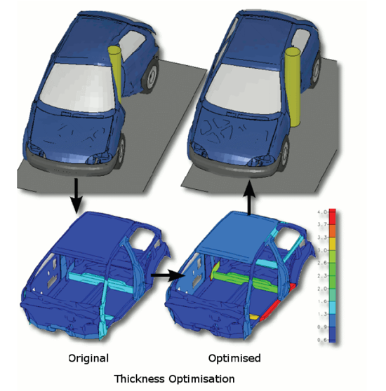
Figure 16: Example of coupling GENESIS and LS-DYNA: Vehicle panel thickness optimisation (sizing) for both static body torsion and side pole impact (LS-DYNA). Results: Torsional stiffness maintained whilst pole intrusion reduced from 600mm to 300mm. Mass increase 39 kg.
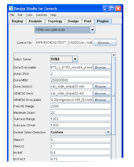
Figure 17: GENESIS to LS-DYNA interface (supports all capabilities of GENESIS optimisation including Topology, Topometry, Topography, Size and Shape)
Finally, Figure 18 and 19 respectively show examples of the Freeform and Autorib capabilities in Genesis. The Freeform is a special case of shape optimisation (with fewer restrictions on the mesh morphing functions) and the Autorib option allows users to add ribs and optimise the rib design on panels of their structure.
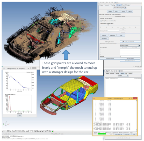
Figure 18: Example of Freeform optimisation with GENESIS (shape directions (top) and analysis (bottom))
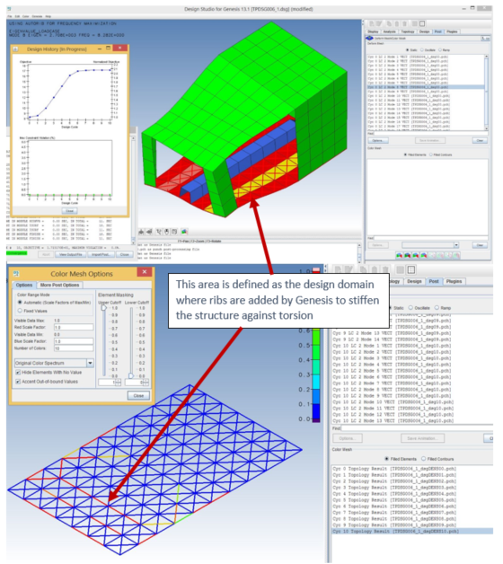
Figure 19: Example of the Autorib option in GENESIS which automatically generates ribs on a design domain to optimise the structure