
Following from Part 1 in our series on how to use reliability physics analysis (RPA) tools to help meet inportant industry standards, today we look at the GMW3172 Standard for “General Specification for Electrical/Electronic Components – Environmental/Durability”. GMW3172 is part of a selection of engineering standards by General Motors (GM) which applies to electrical components for passenger or commercial vehicles and trucks. This standard describes the environmental tests based on mounting location of the electronics unit.
The general/universal Environmental test flow is as shown in the Figure 1 below. Engineering simulation can be used to predict Mechanical and Thermal Fatigue in Test Leg 1 and Test Leg 2. The unique capability of Ansys Sherlock is that it can generate the life curve of the device after a combination of thermal and mechanical shock tests.
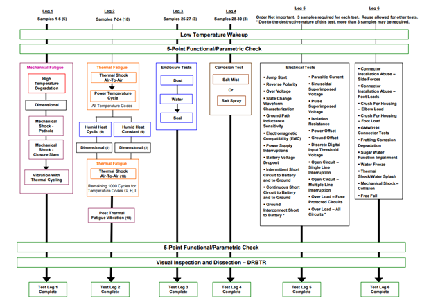
Fig 1: Universal Environmental/Durability Test flow for design validation with Mechanical and Thermal Fatigue covered directly by Engineering Simulations
So would “Mechanical Fatigue” in Leg 1 be a combination of Vibration and Mechanical Shock. Depending on the requirements, inputs are organised in code letters (Tab. 1) for the different analysis types. The inputs for Shock can either be “collision” or “pothole” types.
Leg 2 is the “Thermal Fatigue” which refers to Table 2 is a combination of Thermal Shock Analysis and Thermal Cycling to be setup in Sherlock. Code letters in Table 3 refer to minimum and maximum temperature loads. An example for the input for Code C be seen in Figure 2.
Each electronics unit is represented by a code. The different letters in the code define what test procedures and temperature profiles must be used to comply.
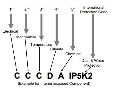
Fig 2: Code Letter Sequence Requirement
In Sherlock it covers the Mechanical and Temperature loads and the code for it as follows, an example of each of the loads is shown as to what can be the input for Sherlock analysis Figure 3 & 4.
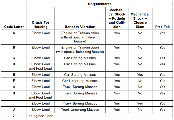
Tab. 1: CODE letters for Mechanical loads
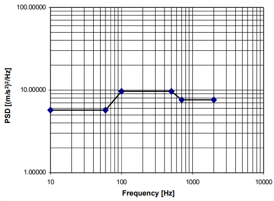
Fig 3: Random Vibration Profile for Engine or Transmission
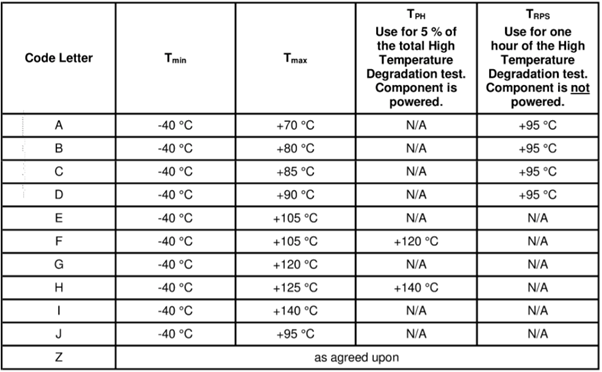
Tab. 2: CODE letters for Temperature loads
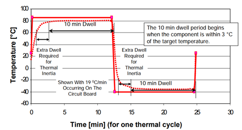
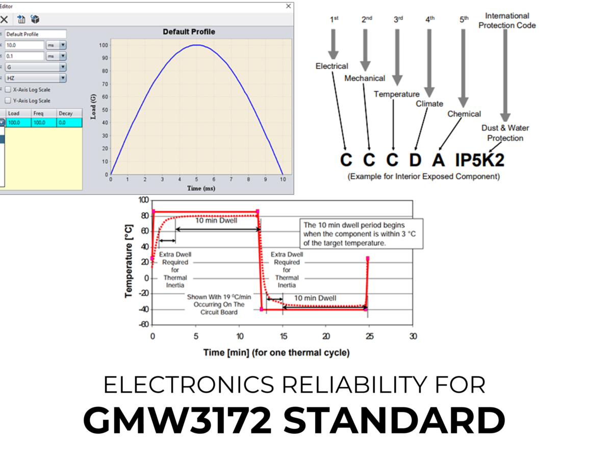
Fig 4: Thermal shock Profile for Temperature CODE Letter “C”
Similarly, the standard evaluates for mechanical shock pulse for Pothole and collision as per the data shown in Table 3 & Table 4 respectively. These can be used as input in sherlock to determine the stress, strain on the components and on the PCB itself deriving the life curve for reliability. Figure 5 shows how the shock pulse can be represented within Sherlock.
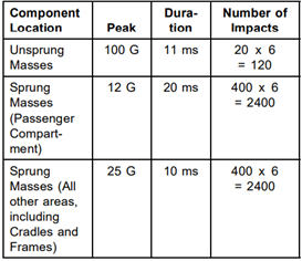
Tab. 3: Mechanical Shock – “Pothole”
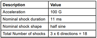
Tab. 4: Mechanical Shock – “Collision”
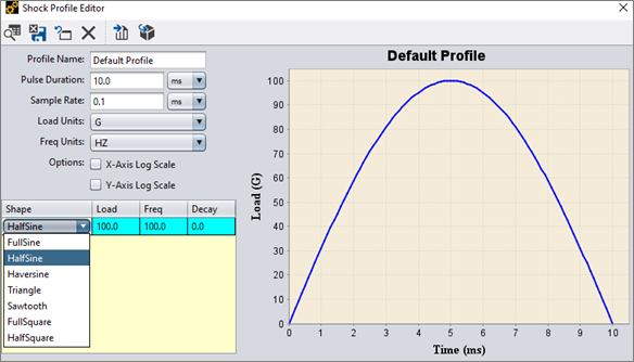
Fig 5: Shock profiles in Sherlock: Users can utilize an easy-to-use Editor to generate the different profiles from Load, Frequency and Decay.
Importantly, the GMW3172 standard highlights that the FE analysis should be used as a Tool to aid for the design reliability and should be one of the earliest activities after the initial part selection and placement as part of the PCB design process.
LEAP has recently assisted Australian companies to use Ansys Sherlock to meet the GMW3172 standard for solder fatigue analysis (temperature cycling) for local projects, so we have considerable recent real-world experience in this area. If you are working to meet GMW3172 standards for your product or component, contact your local LEAP office for a no-obligation discussion on how you can take advantage of simulation to achieve this.

Read our next blogs in this series on Electronics Reliability, where we share some examples on how to implement these procedures in our Reliability Physics Analysis (RPA) Tool for specific standards such as:
You can also learn more here about the range of Ansys engineering software design to assess Electronics Reliability supported by LEAP.