
We recently sat down for a (socially distanced) chat with Luke Mosse, Specialist Applications Engineer at LEAP with 15 years experience in Explicit Dynamics simulations. Our discussion aims to learn how explicit dynamics simulations are used to meet stringent MIL standards for fatigue, crash and blast scenarios.
Luke, you’ve worked on many complex projects involving crash, blast and fatigue simulations to help military vehicles meet MIL standards – first, can you provide some background to the MIL standards you typically work with?
A lot of MIL standard test were developed many years ago before fully transient simulation was readily available. They were often developed for equivalent static load cases; for example, instead of doing a blast simulation test, a simple 200 G (Gravity) static load test would be applied and considered to be the equivalent of a blast for the purpose of the Finite Element simulation. With recent advances in simulation solvers and available hardware, it is much easier to conduct an accurate simulation of a more realistic scenario – which both meets the current MIL standards and provides a better indication of the vehicle’s survivability of a blast or predicted fatigue life under given scenarios.
Many of our clients have experimental accelerometer data – they conduct blast tests during which they measure accelerations at various locations in the vehicle – and we apply those directly in our simulation. So, we don’t have to actually simulate the blast, but can replicate the dynamic effects of the blast on all key components on the vehicle.
How is LS-DYNA suited to simulations being used to these MIL standards?
Based on my experience, LS-DYNA is ideally suited for these blast & crash applications owing to the work that’s been put into the code over many decades at LSTC (which was recently acquired by Ansys), as LS-DYNA was in fact originally developed for blast & projectile simulations. For background, LS-Dyna is a highly dynamic, explicit-based finite element solver, with both a pure structural and a coupled Euler-Lagrange approach that allows you to simulate either just the structure or the blast-plus-structural response with coupling interaction between them. Also, with LS-DYNA having been developed heavily for automotive industry, it has the added benefit of having lots of in-built automotive-based features to model joints, airbags, seatbelts and dummy models – which were all developed for automotive originally, but can be easily applied to vehicles incorporating MIL spec specifications.
You mentioned the accelerometer data can be used by OEMs and suppliers to meet the MIL standards, instead of using simpler load cases. How do you handle & process this accelerometer data so it can be used in these simulations?
 Usually the measured accelerometer data is very high fidelity and can include a lot of noise, so the curves have a huge number of data points and need to be reduced to a manageable amount of data. In some cases the accelerometer history needs to be reduced from hundreds of thousands to a few thousand data points, that can then be defined as a load curve in simulation. In doing so, we need to reduce noise and smooth the data. We recommend and use nCode GlyphWorks to do this – which allows us to still accurately represent the time history, but through filtering and noise reduction we can make the data more useable for our simulation. Certainly, nCode GlyphWorks is light years ahead of trying to use something like Excel when you’re trying to work with these enormous data sets. GlyphWorks has in-built tools designed for this exact kind of data processing – such as the Frequency Spectrum glyph for generating a PSD from time series data; as well as Sample Rate Adjust tool which changes the sample rate to convert massive accelerometer history curves to something more usable in LS-DYNA. There are also very useful filters in GlyphWorks for cleaning the accelerometer data such as Butterworth, Kalman, & Fast Fourier filters.
From your experience on many of these kinds of projects, why do OEMs and suppliers look to use simulations to meet these MIL standards, instead of just physical testing?
It really comes down to the cost savings – especially if you’re dealing with a blast analysis. Simply put, it is incredibly expensive to completely destroy a vehicle – especially a military vehicle which can cost over a million dollars each! Imagine the complexity of a fully-equipped military vehicle which needs to be comprehensively instrumented – with multiple accelerometers and fitted out with test dummies. Because it is so expensive, our customers often plan to blow up each individual vehicle multiple times – placing blasts at different wheels, etc.. to try to get the most out of each one.
With simulation, you also avoid the risk of making mistakes when instrumenting these critical test – if a physical test is not setup properly, you might lose everything and have to repeat it. With simulation, you can do whatever you want, as many times as you like, and repeat things with even small tweaks – essentially, you can have an infinite number of possibilities and as many variants as you want, without having to physically build anything or instrument each vehicle – so you can avoid all these associated costs and the time required to setup and conduct physical tests.
So the cost of setting up these tests can be huge but, in your experience, how do simulations compare to a physical test in the amount of time required from start to finish?
 These days, we’re lucky that companies have the full 3D manufacturing CAD which is readily available, so it’s just a matter of preparing this CAD for analysis in LS-DYNA, which can be done in just a few days. Once you have this baseline model, any variants can then be simulated very quickly – you can vary the explosive strength, location of blast, terrain conditions (soil, concrete) or anything else. Repeating multiple variants in physical tests can be incredibly expensive and time consuming, and also requires many more staff to complete all that work.
Not to mention that in the world of defence, even just getting clearance to blow up a vehicle is difficult! There are also very few specialised sites available in Australia to conduct these kinds of tests.
What are the vibration fatigue analysis requirements in the MIL standard?
The relevant MIL standard is 810G which specifies procedures for physical testing methods and doesn’t explicitly mention simulation. So in concert with our customers, part of our role as an analyst involves interpreting the lab test procedures specified in the standard so that we implement FE simulations that are accurately representative of the specified lab tests. Notably, there are a number of limitations in physical lab testing which don’t apply to us when doing simulation, such as:
– the inability of some shaker tables to vibrate in multiple directions and over the required frequency ranges
– the need to calculate a short duration exposure test that is equivalent to an unfeasibly long test.
– constraints relating to the physical size of the equipment available and/or extra costs associated with larger test beds.
The standard provides you with power spectral density (PSD) curves for a range of vehicles over various terrains – but in reality, it is just as easy for us to specify a measured PSD – which is what we usually do as our customers typically have very good data in this regard.
So is it challenging to work with this measured PSD data?
PSD curves – also known as ASD or Acceleration Spectral Density curves – are a measured acceleration history from driving the vehicle on different terrains; data which is then processed and turned into a frequency domain data. This data is what is then used in the vibration fatigue analysis, often involving multiple terrains over multiple duty cycles. Typically, a customer will require assessment of something like 4 different terrains, and they would expect the vehicle to have a particular duty cycle for each terrain applied in the fatigue analysis. So we work with PSD curves each with x, y, and z data for each of the terrains, which are applied in the specified duty cycle and we calculate a fatigue life for each. If needed, these simulations can easily be re-run with different combinations or durations – eg. if terrain #1 needs to be assessed for a longer duration, we can easily re-run the vibration fatigue analysis. A tool like GlyphWorks is critical to convert the measured acceleration data into an PSD curve.
Can you explain the workflow for simulation of vibration fatigue in more detail?
Starting with GlyphWorks to convert acceleration data into PSD curves, we then run simulations in Ansys for modal & harmonic analysis, followed by fatigue analysis in Ansys nCode. The key steps are:
- Modal analysis: A free vibration modal analysis to obtain the natural mode shapes and frequencies of the model.
- 1G harmonic analysis. Three modal superposition harmonic analyses applying a sinusoidally varying acceleration load in each orthogonal directions (vertical, longitudinal, transverse).
- PSD based fatigue. The three harmonic analysis results are scaled by the vertical, transverse and longitudinal PSD curves.
- An appropriate PSD cycle counting method is used to estimate the number of cycles and stress levels that the structure is exposed to in the loading.
- Two separate fatigue analyses are conducted on the parent metal of the parts and on the welds. The BS7608 method is used to calculate the fatigue life of the welds.
So in essence, the 1G harmonic results are fed into Ansys nCode and combined with acceleration spectral density and material properties, will calculate the amount of damage experienced by every each element in the FE model. The stress-life curve from the material data, combined with PSD and harmonic analysis results, are used together to calculate the damage accumulation and arrive at a calculated fatigue life.
nCode is not only a FE-Based Fatigue Solver but has many modules for digital signal processing and vibration analysis. With nCode, you can easily scale up your test and experimental data processing workflow from a couple of measurement channels to thousands of channels. nCode is data logger agnostic and so input data source may include FE-Results files, sensor data recordings, video recordings, GPS data recordings, vehicle CAN-Bus data, etc.
nCode optimised it’s algorithms to process large combination of data sets in record time with a high level of accuracy and repeatability. The user develops data flows in nCode which is easily transferable, auditable and scalable to other projects and larger data sets. It is even possible to generate a reporting template and generated automated test or fatigue assessment reports within nCode.
Can you explain the importance of proper weld modelling in this kind of fatigue analysis?
Weld analysis can be difficult and is a contentious topic – there are always variations in a real-world manufactured weld, so simulation needs to be slightly conservative. Many techniques are used to analyse welds, for example in the automotive industry there is the Volvo method which is specific for fatigue in thin sheet metal parts. In thicker metal parts you typically use the BS6078 standard, which was developed from actual tests of welded specimens – it’s not analysing the weld itself, it is extracting stress from the material adjacent to weld and uses a specific set of stress-life curves developed from experimental tests to predict when the weld itself will fail. So this gets around a lot of the variation that you can get in welding, providing the analyst with a standard analysis technique that can be used, including specific mesh connection methods and mesh sizes in each region.
In your experience, how often is the region of the weld the cause of failure in these studies?
Most of the time failure is predicted in a weld first, very rarely do we find that the parent metal fails before the weld fails. Generally, we conduct two separate analyses – one analysis looks at the adjacent metal using specific stress life curves for the parent metal; and then we do a separate analysis of just the welds using the weld standard BS6078, which uses a different set of stress life curves and different methods. The combination of these two approaches gives us confidence in identifying the likely failure mechanisms for any component.
Whilst military work can be a sensitive topic, are you aware of any examples that interested engineers can learn from?
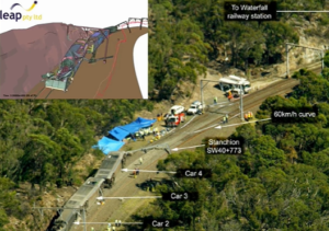
Understandably, the details of this work can be a closely guarded secret in the industry, but you can see some examples of customers who have shared part of their work to educate an engineering audience. For example, at CONVERGE 2019 last year in Melbourne, we hosted a presentation from Thales who shared some fascinating insights into the work they have done for the Bushmaster and Hawkei vehicles, including showing videos showcasing the excellent agreement they get between their simulations and their physical blast tests (see above – Explicit Dynamics simulations start at 12:59).
Want to learn more?
To speak with one of LEAP’s expert in ANSYS Explicit Dynamics simulation tools, visit our LS-DYNA page on the LEAP website and submit an enquiry to discuss your specific project requirements.