
Engineers involved in the design of most electronics must ensure their device is safe to use and operate in compliance with FCC rules and relevant industry standards – which may include standards for automotive (SAE J3168 and/or GMW3172), military (MIL-810G), or aerospace (DO-160G). At LEAP we commonly assist with assessments of EMC and EMI which are an important subject on their own and often require design solutions, guidelines, and simulation practices (leading to standardised test procedures for future products). In parallel to these EMC challenges, another critical design aspect for any electronics device is to ensure it’s durability and reliability across the entire service life.
Standards are a great way to test your PCB for influences representing real-world scenarios under reproducible conditions – especially useful to compare different designs in an apples-with-apples comparison to allow engineers to understand and quantify the predicted reliability of a product. Standards also support the use of accelerated lifetime tests (HALT/HASS) – for example, a product that experiences one load cycle per day for 1,000 days can be tested in six weeks using 15min ramps and 15min dwells to achieve 24 cycles per day. Life tests can also be accelerated by applying stresses that are beyond normal operation while maintaining the same dominant failure mode.
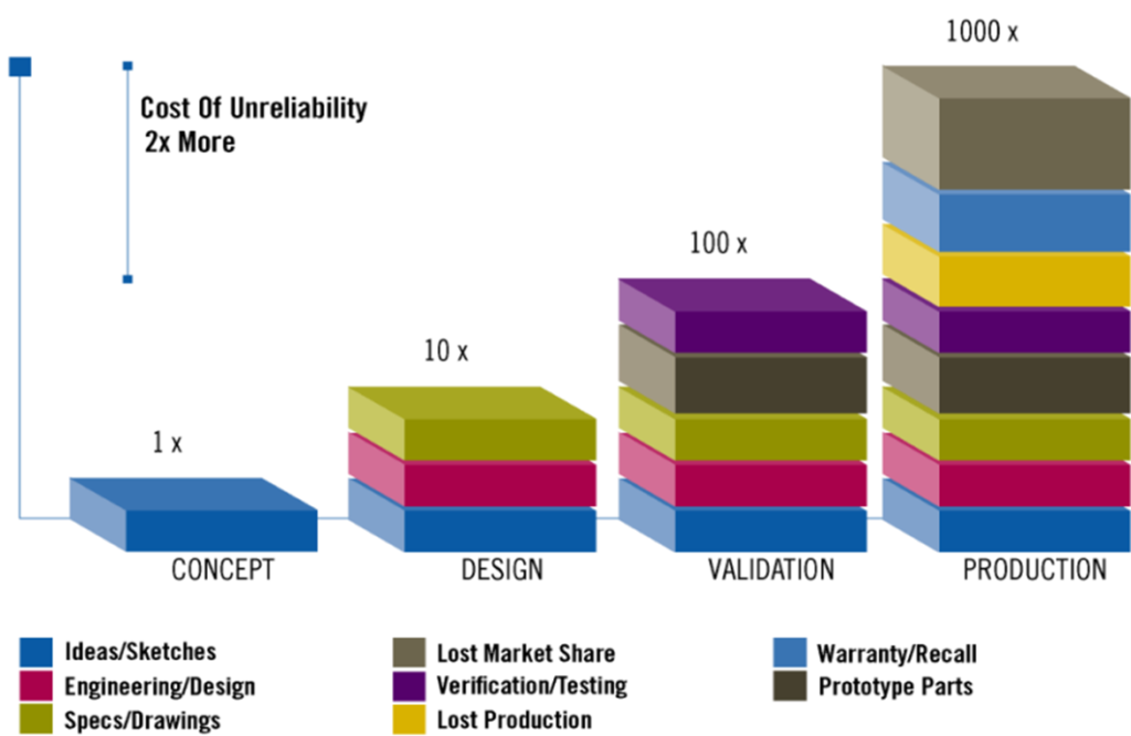
Fig 1: Reduce Costs by improving reliability upfront (Source)
What can be done to accelerate electronics product development even further? If you look at the chart in Figure 1 you see that the most cost-effective way of implementing reliability into your product is by completing it during the concept and design phase. In this blog series, we aim to demonstrate how engineering simulation in conjunction with standards is helping electronics product designers to deliver more cost efficient and faster development cycles.
At LEAP we now have considerable experience in helping our industry customers to implement a Reliability Physics Analysis (RPA) Tool which helps both:
- identify potential reliability issues early, and
- determine a concrete lifetime prediction for your printed circuit board (PCB) assemblies.
This addresses the question of reliability upfront during the concept phase (when the cost to fix issues is low) and allows for further environmental testing in alignment with standards during the design stage. It is estimated that this reduces 20-50% time in PCB reliability prediction at component, board and system level and reduces overall costs by ~50% for a design that meets required regulations. In the simulations performed in Fig 2, the analysis is sped-up by using native ECAD data containing the stack-up of the PCB, materials and traces and a full set of data for each individual component coming from a sophisticated in-build component library.
Typical results are not just mechanical stress, mechanical strain and displacement alone but most importantly probability of failure and time-to-failure (TTF) over a user defined service life for individual components but also on a board level.
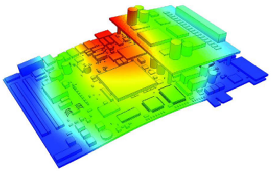
Fig 2: Displacement of a PCB due to Mechanical loads.
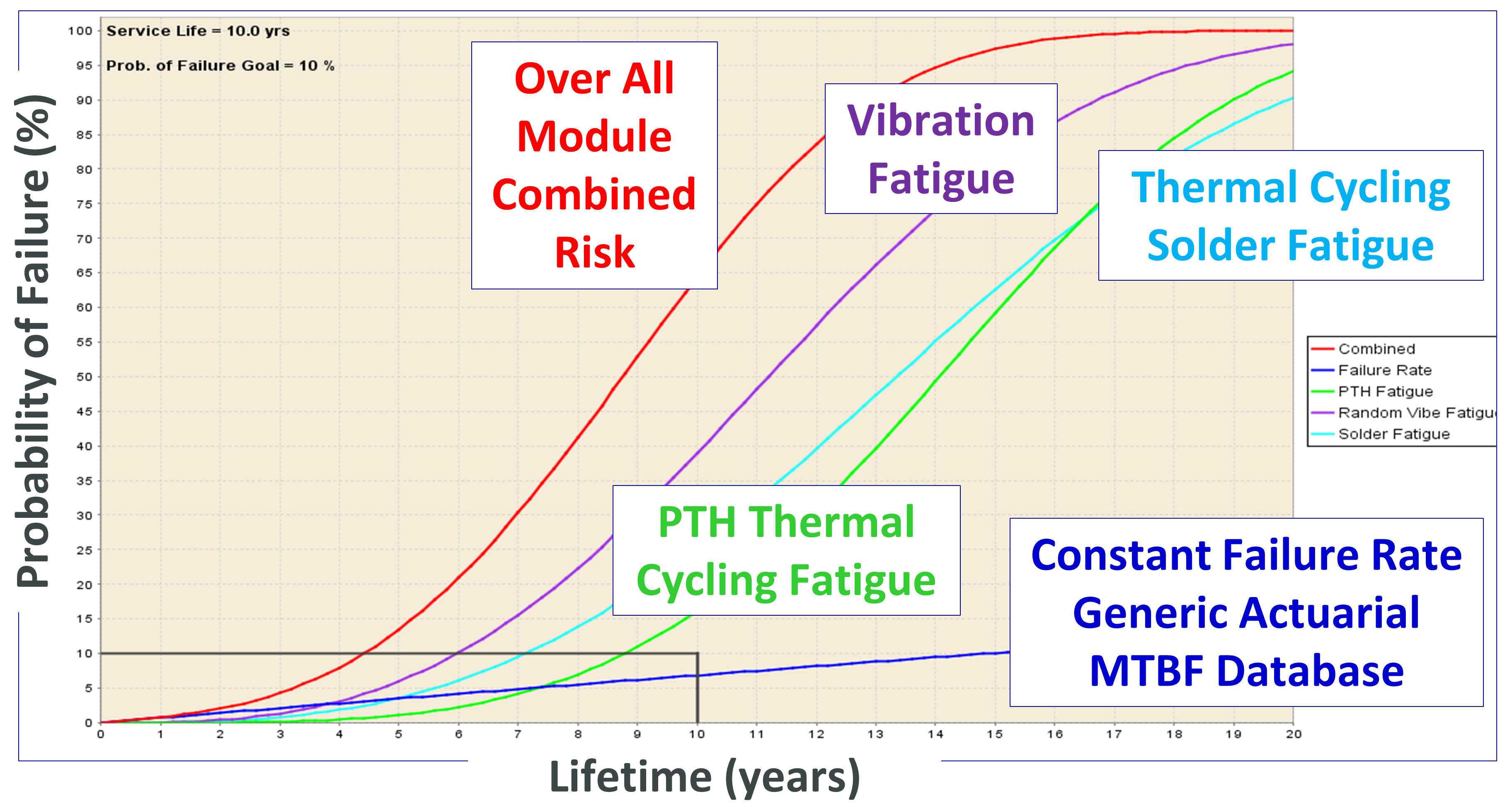
Fig 3: Life curve of the PCB for different Analysis for a defined Service life of 10years and a user defined goal for the probability of failure of 10%.
Those results are key to make further design decisions and are retrieved by a combination of physics equation, Finite Element Analysis (FEA) and materials knowledge to compute RPA-based predictions at the component, board, and system-level. In Figure 3 you can see that the Tool predicts the bespoke results for each failure mode but also an overall combined risk for all required tests and physical phenomena.
The different standards require several different aspects for environmental testing, such as humidity, waterproofness, and impact of dust; all of which can be implemented through Computational Fluid Dynamics (CFD). The EMI and EMC pre-compliance with Ansys Electromagnetic PCB simulation tools is solved with transient or static Electric Solvers. SAE J3168 also includes Life Limited Microcircuit Aging & Wearout, defined in Section 6.5.5.
The workflows discussed above covers the following main three mechanical tests presented in Table 1.
| Test | SAE J3158 | MIL-810G | GMW3172 | DO-160G |
| Thermal Shock & Cycling | 6.5.1 (under revision) | METHOD 503.5 [Figure 503.5-1 single shock (1/2 cycle)] | 9.3.1.4 (together with Random Vibration) | Section 5.0 |
| Vibration Testing | 6.5.2 (under revision) | METHOD 514.6 | 9.3.1 Random Vibration | Section 8.0 |
| Shock | 6.5.3 (under revision) | METHOD 516.6 | Section 9.3.3 | Section 7.0 [Fig 7.2 Terminal Saw tooth shock pulse configuration] |
Table. 1: Relevant sections of standards addressed by Sherlock RPA Tool
Read our next blogs in this series on Electronics Reliability, where we share some examples on how to implement these procedures in our Reliability Physics Analysis (RPA) Tool for specific standards such as:
You can also learn more here about the range of Ansys engineering software design to assess Electronics Reliability supported by LEAP.