
Following from Part 1 in our series on how to use reliability physics analysis (RPA) tools to help meet important industry standards, today we look at the DO-160G standard which covers “Environmental Conditions and Test Procedures for Airborne Equipment”. PCBs installed in any airborne vehicles can be used to perform the vibrational and solder fatigue analysis in Ansys Sherlock to predict the life cycle/ Time-to-failure (TTF) of the components and the board itself, as per these standards.
The following three categories of tests presented in the standard can be performed:
Section 5: Temperature Variation
Section 7: Operational Shock and Crash Safety
Section 8: Vibration
Section 10: Explosion Proofness, Section 16: Power Input, Section 20: Radio Frequency Susceptibility (Radiated and Conducted) and Section 25: Electrostatic Discharge can partwise be handled by Simulation Tools and represented in design studies.
Depending on the altitude in which the aircraft operates, environmental tests fall into different categories and each of them have their specific range of temperatures to perform the analysis. These temperature tests replicated in Ansys Sherlock would predict failures due to high stresses from a mismatch of thermal expansion material properties.
The purpose of Vibration test is to demonstrate that the equipment complies with the applicable equipment standards (including durability requirements) when subjected to mechanical load levels specified aircraft type, test category and aircraft zone location as shown in Table 1.
| Category | Aircraft Type | Standard Vibration | High Level – Short Duration Vibration | Robust Vibration |
| S | Fixed-Wing | 1 Hr/Axis sine or random at perf. Level | NA | NA |
| H or Z | Fixed-Wing | NA | High g/low f sine sweep each axis | NA |
| R | Fixed-Wing | NA | NA | Sine of 3 Hrs/Axis less 30 min/dwell (max. 4 dwells) or Random at perf. Level (minimum of 10 minutes) and 3 Hrs Endurance level (repeat in all 3 axes) |
| R or U | Helicopter | NA | NA | Section 7.0 [Fig 7.2 Terminal Saw tooth shock pulse configuration] |
| U2 | Helicopter | NA | NA |
Tab. 1: Vibrational load criteria
There are different test curves for each aircraft types and it can be used to predict the life cycle of the PCB in sherlock for each of these loads. As an example, one of the PSD used for fixed wing aircraft is shown in Figure 1. The legend next to it gives the test curve for different cases (B2, B, B3, C, D, E) and an example of how that can be incorporated within sherlock is shown in the figure next to it. The vibrational loads or the PSD can be brought in sherlock and used for vibrational analysis to predict the life curve on individual components on the PCB and life curve of the PCB itself.
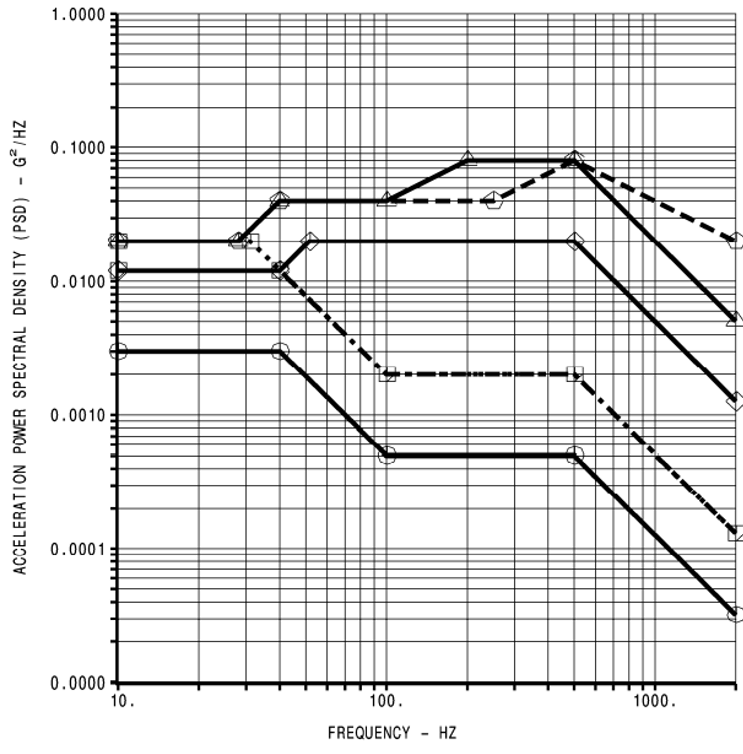
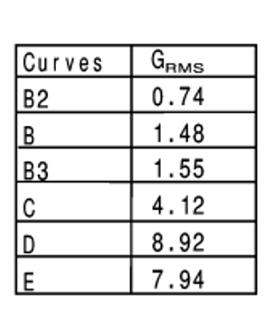
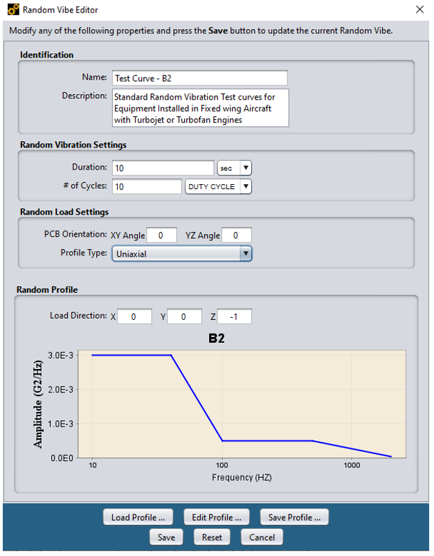
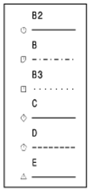
Fig 1: Standard Random Vibration Test Curves for Equipment Installed in Fixed wing Aircraft with Turbojet or Turbofan Engines(top); Test curve B2 represented in Sherlock (bottom)
The operational shock test verifies that the equipment will continue to function within performance standards after exposure to shocks during nominal aircraft operations, these shocks may occur during taxiing, landing or when the aircraft encounters sudden gusts in flight. These are shown in the Figure 2. These are used as input for the reliability analysis in sherlock to determine the probability of failure and life curve of the board for shock loads.
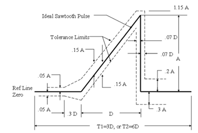
| Test (impulse) | Peak Value (A) (g) | Nominal duration (D) (ms) |
| Standard operations | 6 | 11 |
| Low-frequency operational | 6 | 20 |
| Crash safety | 20 | 11 |
| Low frequency Crash safety | 20 | 20 |
Fig 2: Terminal Saw Tooth Pulse Configuration & its Tolerance Limits were D=duration of nominal pulse, A=peak acceleration of nominal pulse, T1=minimum time during the pulse should be monitored for shocks produced using a conventional shock testing machine, T2= minimum time during the pulse should be monitored for shocks produced using a vibration generator.
If you are working to meet DO-160G or other similar industry standards for your product or component, contact your local LEAP office for a no-obligation discussion on how you can take advantage of simulation to achieve this.

Read our next blogs in this series on Electronics Reliability, where we share some examples on how to implement these procedures in our Reliability Physics Analysis (RPA) Tool for specific standards such as:
You can also learn more here about the range of Ansys engineering software design to assess Electronics Reliability supported by LEAP.