

The Formula Student competition challenges engineering students from around the world to design, manufacture, market and race a small, open wheeled formula style racer.
Since its inception in 2000, Monash Motorsport has competed in the Australasian competition every year, building a combustion engine powered racer.
Additionally, Monash has been fortunate enough to compete against the best in the world, taking part in the German, Austrian and UK competitions in 2006, 2010, 2012, 2014, 2016 and 2018.
In 2016, Monash began developing an electrically powered car alongside the teams combustion car. This year served as a research and development year, allowing time for the team to learn, analyse and decide on the core concepts for the 2017 vehicle.
Adopting the “one team, two cars” mantra, Monash decided to keep it simple for their first electric vehicle, and maintain as much commonality between the two vehicles as possible.
A single, chain driven Emrax 228 Permanent Magnet Synchronous Motor (PMSM) and Bamocar D3 Inverter were selected as the core of the powertrain, with a cross compatible drivetrain shared with the KTM 690 powered combustion car. This simple approach was crucial to the following success of the two vehicles, allowing the team to shift resources to either car when needed, and share technical knowledge and data.
In parallel with the construction, and testing of the of the 17/18 vehicles, Monash maintained an R&D group, who with support of sponsors, Semikron, Regal Beloit and LEAP Australia, have been developing a custom motor and inverter package for future vehicles. A custom powertrain solution offers not only performance benefits, but also improves packaging flexibility (particularly for in-hub motor solutions), maintenance and technical understanding, at the cost of additional complexity and development time.
Whilst it is possible to use analytical methods to design electric motors, numerical methods utilised by software such as ANSYS Maxwell give higher accuracy and simplify development, especially for the complex geometries and saturation effects present in high power motors. ANSYS Maxwell can also be used for power electronics development, simulating key design parameters such as parasitic inductance and current density distributions.
FEA (Finite Element Analysis) is already used extensively on the team for mechanical (structural) and aerodynamic design, extending this to electromagnetic and electrical design allows for faster, more accurate and more robust designs.
ANSYS Maxwell for Motor Development
3D ANSYS Maxwell
The Axial flux PMSM has been designed in conjunction with Regal Beloit Motor Corporation and RMIT Electric Racing, who are developing an integrated planetary gear system to suit the Motor.
Inherent in the Motor design is a tradeoff between efficiency and mass. A larger motor will, in general, be more efficient than a smaller motor, and vice versa. To balance the value of mass and efficiency, a mass-efficiency equivalence was created, taking into account the effect of efficiency on:
- Additional mass required to store the energy (energy density of cells)
- Mass feedback loops, additional mass requires additional energy
- Regenerative braking – efficiency is effectively applied twice
- Efficiency points at competition
- Value of mass in points at competition
The result of this was an equivalence of roughly 1% motor efficiency being equivalent to 1kg of mass, or for a quad motor system 1% motor efficiency corresponds to 0.25kg of mass (per motor).
By setting up a parametric design in ANSYS Maxwell (parameterising values such as slot width, slot depth, stator yoke thickness, magnet thickness etc.) and sweeping parameters, the effect of varying parameters on effective mass can be analysed. ANSYS Maxwell makes this easy through the “Optimetrics” functionality, which will automatically vary parameters and save the simulation results.
The Motor has been designed to suit a regen-capable all wheel drive Formula Student racer with the following requirements:
- >350Nm of Torque at each wheel
- Low effective mass
- Packageable into a wheel shell (outer diameter restriction)
- Integrated planetary gearbox (inner diameter restriction)
- Top speed of ~115 km/h (equivalent to a wheel speed of 1300 RPM)

The final design meets the requirements with a 5:1 reduction and a motor torque of >70Nm, achieving an efficiency of 92-96% in the designed operating range (which is around 40 to 80 km/h) at an electromagnetic mass of 3kg (i.e. not including bearings, casing and the gearbox).
2D ANSYS Maxwell
ANSYS Maxwell is available for modelling both 2D and 3D electromagnetic systems.
Modelling in 2D is less computationally intensive, however makes implicit assumptions about the symmetry of the model. For example, when modelling a radial flux motor, modelling an axial cross section of the motor is accurate, under the assumption that the motor is long enough for the end effects to have a negligible impact.
Additionally, 2D simulations can be used effectively when the model is too complex, and you are limited by computational resources. A good example of this is analysing the eddy effects in individual conductors.
When modelling motors in FEA, the motors are designed with an equivalent MMF (magneto-motive force) or Ampere turns. A motor (electromagnetically) doesn’t care whether you have 100 turns with one amp, or one turn with 100 Amps of current.
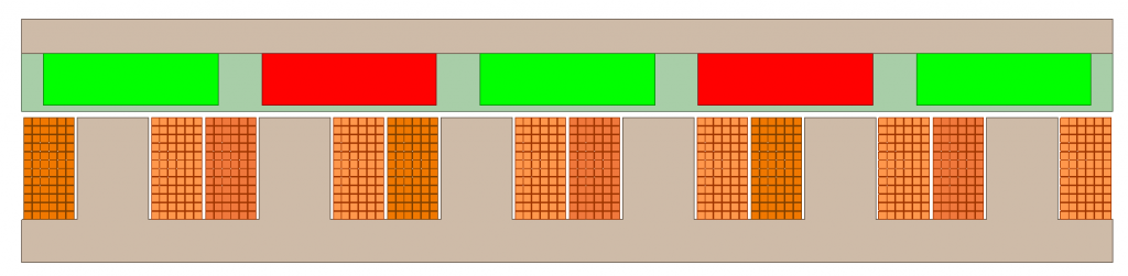
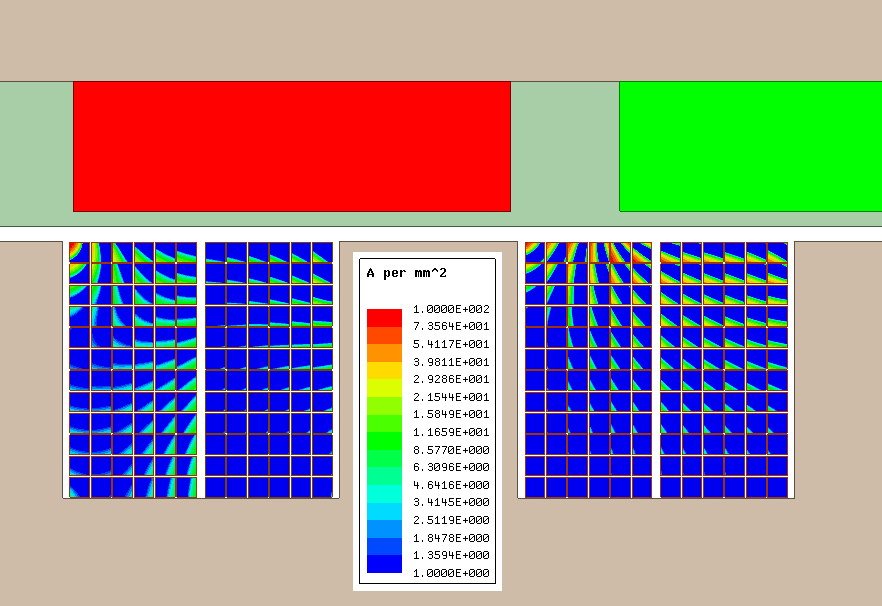
However due to factors such as slot leakage (flux leaking between stator teeth due to saturation in the core) and the movement of the magnets over the slots, there can be time varying fields in the slot itself. These time varying fields induce eddy current loss in the conductors, which won’t be modelled in an equivalent MMF model.
By modelling the individual conductors in a slot in 2D, some accuracy is lost due to the aforementioned assumptions of symmetry, but a much better estimate of the AC copper loss can be determined. The field distribution inside the coils (and the resulting AC current density distribution – 90 degrees out of phase) can be seen below.

ANSYS Maxwell 3D for Busbar development
When developing any switching circuit, a key design parameter is the switching loop inductance.
The switching loop inductance, is the inductance between the power electronic switches and capacitor bank. This inductance induces a voltage according to:
In a switching circuit, there are two main components of loss, switching loss and conduction loss. By reducing the switching time, the switching loss can also be reduced. However faster switching results in a larger inductive voltage being generated, which could potentially damage the Silicon Carbide MOSFETs used in the Inverter.
Initially when attempting this simulation, we were expecting a long and drawn out process.
However the relatively simple geometries of most busbar designs, and the possibility to import geometry from other CAD programs (such as solidworks) meant that it only took an hour to get the value of the switching loop inductance in the existing design.
Through some geometry changes, we were able to simulate a design which had a switching inductance ~10 times lower than the original design (down to ~10nH).
Both designs were validated through the use of an LCR meter to within 5% of the simulated value.
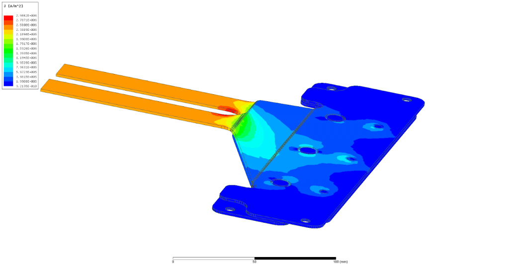
The other key concern in busbar design is thermal management. Depending on the cooling, the maximal allowable current density in the busbar sets a lower limit on the physical size. Physical size, being correlated to mass, is crucial in the design of an inverter for racing applications.
By analysing the current density plot produced in ANSYS Maxwell, we were able to cut out unnecessary mass, and verify our busbar design would not exceed the current density limits.
As an added benefit, ANSYS Maxwell can also evaluate Eddy current and DC loss automatically, when doing a transient simulation.
Monash Motorsport would like to thank Semikron, Regal Beloit and LEAP Australia for their ongoing support, we look forward to further development and success in collaboration with our industry partners.