
The design and construction of composite structures represents a powerful and lucrative industry that is predicted to grow dramatically as demand increases for the high strength, low weight properties possible with composite materials.
Part of the ANSYS Workbench environment, ANSYS Composite PrepPost provides tailored tools for the multitude of composite specific problems that face designers and engineers.
This post will provide an overview of features within ANSYS Composite PrepPost, highlighting the benefits it provides to users.
Ply Tapering
When using shell elements, the creation of variable thickness parts poses great difficulty for traditional layer section definitions. With the use of edge sets in ACP (Pre), varying thicknesses can be easily captured with an intuitive taper angle controlling the drop off of plies from the part boundary.
Uses of this functionality includes angling of sandwich core edges to capture manufacturable geometry or the simulation of scarf joint architecture between components. The use of ply tapering was paramount in increasing model fidelity of a composite bike frame whose real construction utilised scarf joints between each of its components. Modelling of the joint architecture limited numerical stress concentrations and captured a more accurate stress field at the component joint.
Component joint modelling in bicycle headset using ply tapering, (a) butt joint, (b) scarf joint
Parameterisation
Parameterisation of layup properties is key in the process of design optimisation. ANSYS Composite PrepPost includes functionality for a wide array of parameterisation including floating numerical inputs such as fabric thickness or fiber angle, integer values such as number of plies and discrete parameters such as material type or ply activation.
All parameters are available for what/if testing or integration with DesignXplorer optimisation or sensitivity studies, guiding engineers to higher performing, more efficient structures.
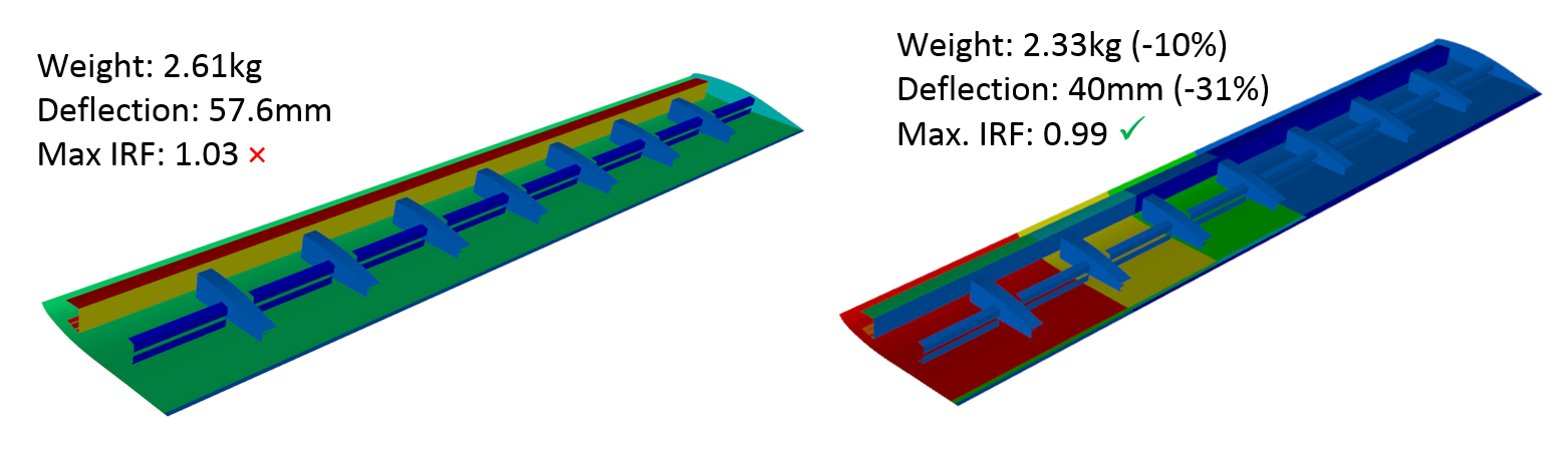
Structural thickness of composite wing for; (a) baseline model, (b) optimised model
Progressive Damage
Post failure response of composite structures has been a focus of intense research. The orthotropic nature of laminate material means failure mechanisms are far more complicated than those experienced in metallic structures.
The ability to capture the numerous failure modes possible with composite damage is facilitated within ACP using industry trusted failure criteria such as the quadratic Tsai-Wu criteria or the phenomenological Puck criteria. Failure detection is coupled with Chang and Chang derived constant knockdown post failure property degradation capturing the softening of the composite with failure.
Post processing tools within ACP (Post) can visualise failed elements capturing fracture shapes and the propagation of damage throughout a structure.

Final fracture shape for Iosipescu shear test sample; (a) experimental, (b) numerical
Draping
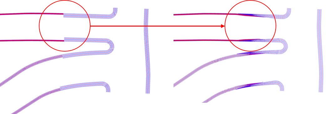
The placement and consolidation of multiple layers of fabric onto complex structures has been observed to effect laminate level mechanical properties. Draping effects such as wrinkling or fabric shearing change the fibre orientation within the ply, effecting its stiffness and load carrying ability.
Draping algorithms within ANSYS Composite PrepPost are available to simulate the fibre distortion of draping and update the elemental stiffness for analysis. Use of this functionality can increase model fidelity, accounting for manufacturing constraints with material placement.
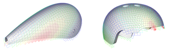
Fibre shear shown in red caused by fabric draping on various bicycle helmet geometries
Extrusion Guides
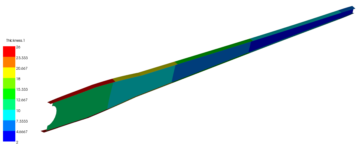
With the use of shell elements for initial model formulation, complexity can arise when defining complex thickness distributions for sandwich cores or thick composite parts. Functionality within ANSYS Composite PrepPost allows the import of a geometry file to be used as a thickness guide when extruding plies. This feature allows complex varying thicknesses to be defined rapidly with the possibility for rapid changes at the geometry input level.
Conversion to solid elements or the use of a thickness plot allows the engineer to visualise the material extrusion and its effect on thickness distribution.
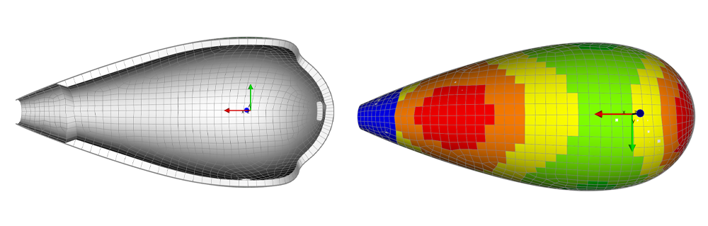
Material distribution from geometry thickness guide used with foam core
Selection Rules
Manipulation of composite fabric shapes can be performed with a variety of selection rules within ANSYS Composite PrepPost, these design tools allow element selection for ply shapes based on defined geometric boundaries such as parallel planes, spheres of influence or tube rules which can follow model edges.
Selection rules can be used to define reinforcement plies without the need for multiple orientated element set definitions, decreasing modelling time and complexity. Full parameterisation support of selection rules allows automated manipulation of ply shapes from the parameter set window or within DesignXplorer.
Use of parallel selection rules for material tapering with a single orientated element set
Fabric Polar Analysis
Analysis of a composite fabrics orthotropic properties is rapidly available in ANSYS Composite PrepPost, allowing engineers to visualise the off axis stiffness to be expected from the fabric type.
Available for individual fabrics and consolidated stack ups of multiple plies, this tool gives a clear graphical representation of material properties as they are being applied to the structure, giving the engineer confidence in their selection and reducing trial and error at the analysis stage.

Fabric Properties for; (a) Unidirectional [0]n, (b) Bidirectional [0,90]n, (c) Quasi isotropic [0,±45,90]n.
Solid model cut-outs
When dealing with complex structures in ANSYS Composite PrepPost it can be advantageous to neglect some model features during meshing and layup such as window cut-outs or channels cut through panel stiffeners. Functionality within ANSYS Composite PrepPost allows geometry import representing cut-outs being made to the structure after the layup process is complete. Automatic mesh splitting and drop off elements capture complex cut-outs and there change to model geometry.
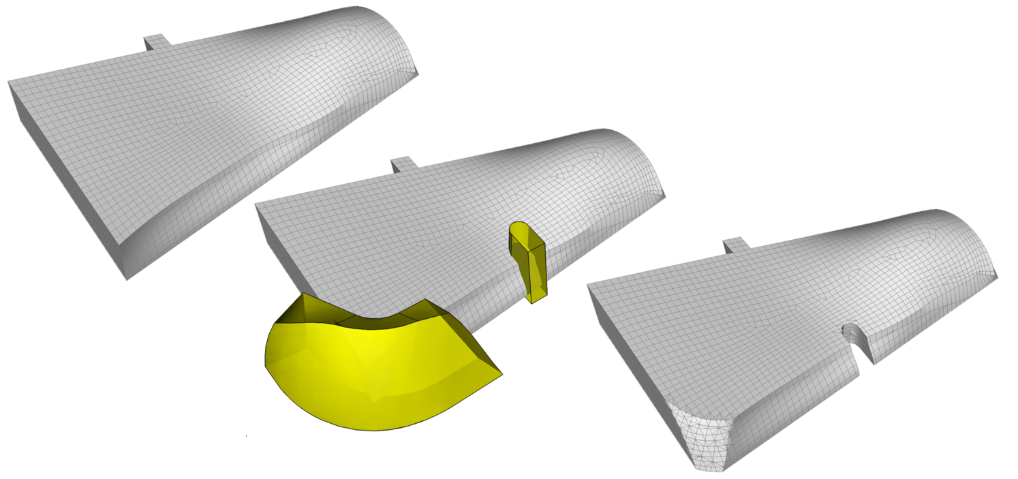
Use of geometry cut-offs on a solid composite structure