
Bolted joints are commonly used to assemble mechanical structures. Modelling bolts for three-dimensional finite element applications has always been a tricky proposition because the details of bolt geometric features usually result in large model size and high computational cost. Therefore, efficient methods to model bolts are always desirable.
The approach to modelling bolts usually involves undertaking the following:
- Prepare geometry: bolt and associated components
- Mesh: Minimum DOF for best representation/ Hex or Tet
- Contact: load transfer/stress
- Load definition:
– Step 1: Apply bolt pretension load
– Step 2: Lock the defined bolt pretension load
– Step 3: Apply in-service loads to structures
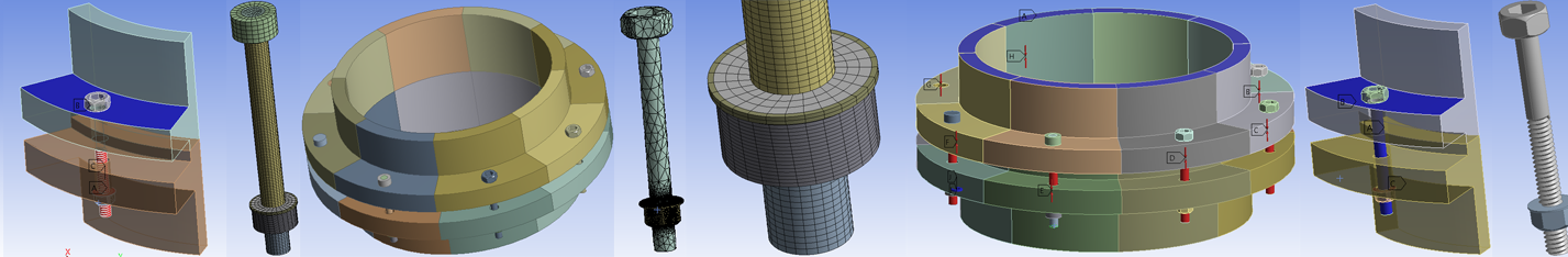
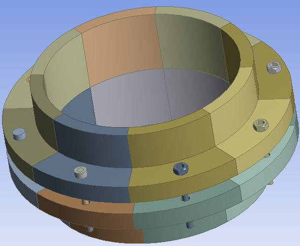
How one prepares the bolt geometry is an essential factor that will influence the subsequent modelling techniques including meshing, contact and analysis settings. This blog summarises eight methods for modelling bolts in ANSYS 15.0. A simple eight-bolt flange model is used for assessing the different methods.
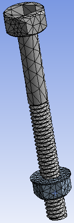
Bolt Model 1:
- Full thread on bolt and nut are modelled;
- Good geometric representation of stiffness if mesh is fine enough;
- Tetrahedral mesh would normally be produced, the element quality on threads need to be check carefully, fine mesh needs to be used on the threads
- Contact between bolt and flange, nut and bolt are defined as any contact type aside from bonded;


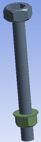
Bolt Model 2:
- Threads on bolt and nut are removed;
- The removal of thread could influence the bolt stiffness subjected to loadings;
- Tetrahedral mesh are used, similar to Bolt Model 1, but less mesh on thread region can be obtained;
- Contact between bolt and flange, nut and bolt are defined as any contact type aside from bonded.

Bolt Model 3:
- Threads on bolt and nut are removed, similar to Bolt Model 2.
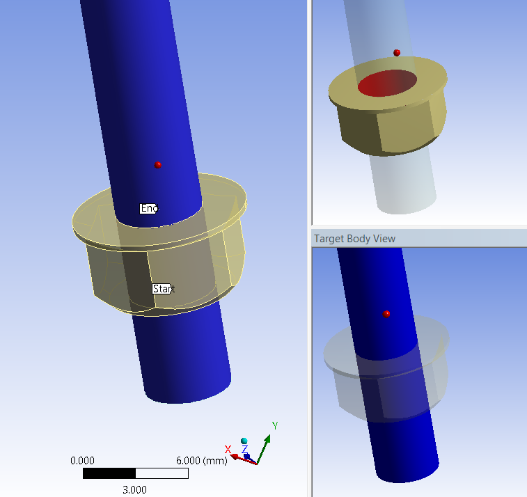
- New bolt thread contact technique in ANSYS 15.0 is applied to define the contact between bolt and nut. This contact method defines all of the thread characteristics. The computational cost for getting similar stresses in thread region is reduced by a factor of 10 compared to Bolt Model 1;
- Tetrahedral elements are used, similar to Bolt Model 1; use contact sizing to increase number of elements in thread area.
- Contact between bolt and flange, nut and bolt are defined as bonded with asymmetric behaviour.


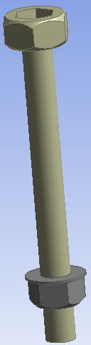
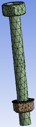
Bolt Model 4:
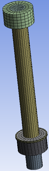
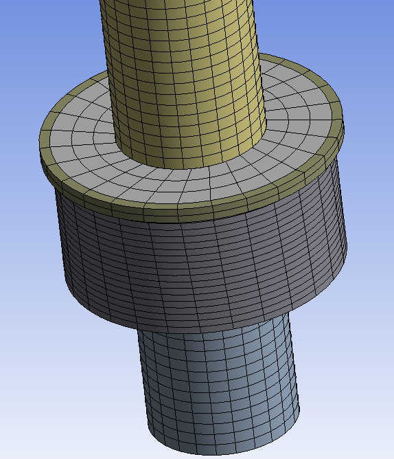
- The bolt and nut are defeatured and sliced to be sweepable bodies;
- Better mesh controls can be applied to generate hex mesh.
- New bolt thread contact technique in ANSYS 15.0 is applied to model the contact between bolt and nut, similar to Bolt Model 3 (recommended 4 elements span 1 thread width).
- Contact between bolt and flange, nut and bolt are defined as bonded with asymmetric behaviour.
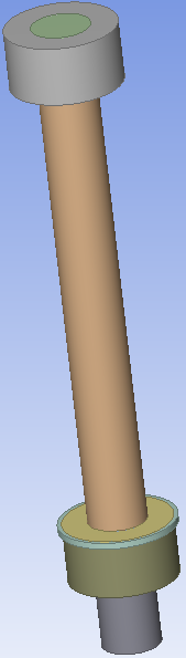
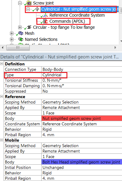
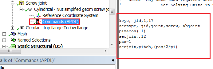
Bolt Model 5:
- Geometry is same as Bolt Model 4;
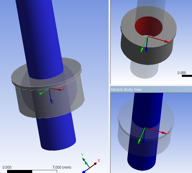
- Bolt thread contact between bolt and nut is replaced by a cylindrical joint
- APDL command is inserted to redefine joint as a crew joint
- Contact between bolt and flange as bonded with asymmetric behaviour.
Bolt Model 6:
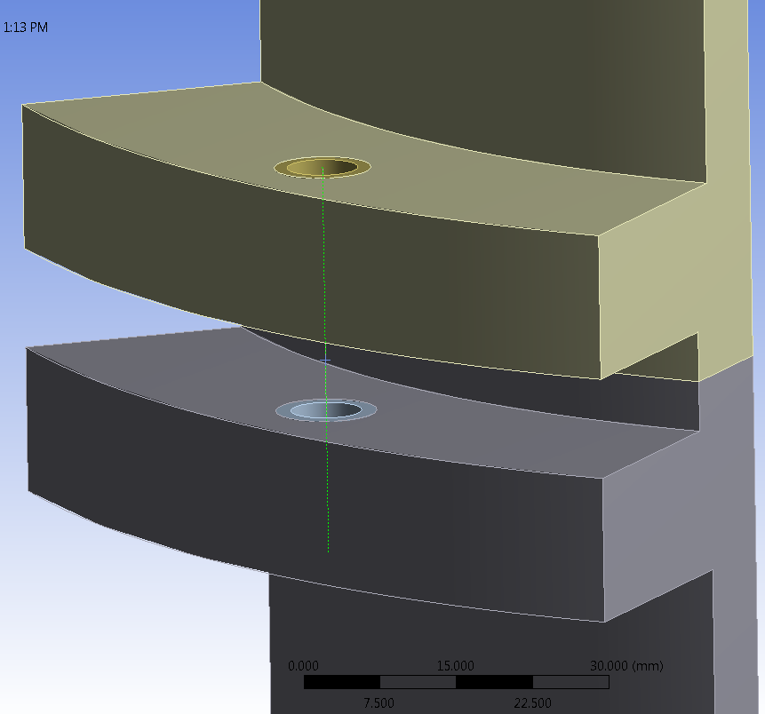
- Bolt joint is simplified and modelled as line body;
- Cylindrical surfaces are imprinted on both upper and lower flange to simulate contact regions;
- Bonded contact (MPC) used to attach cylindrical contact region with ends of line body
- Line body meshed as beam elements, hence reducing model size significantly;
- However, the details of the stress of the bolt joint would not be available.
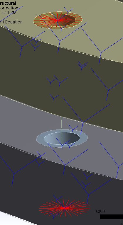

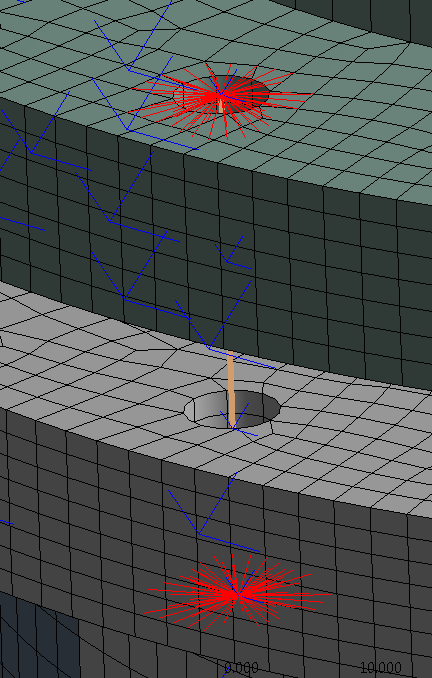
Bolt Model 7:
- Bolt joint is simplified and modelled as line body, similar to Bolt Model 6.
- No cylindrical faces are imported on the flanges.
- Bonded contact (MPC) used to define contact between ends of line body and cylindrical edges of the bolt holes. Pinball radius should be big enough to include the cylindrical edges;
- The details of the stress of the bolt joint might not be avaiable, similar to Bolt Model 6.

Bolt Model 8:
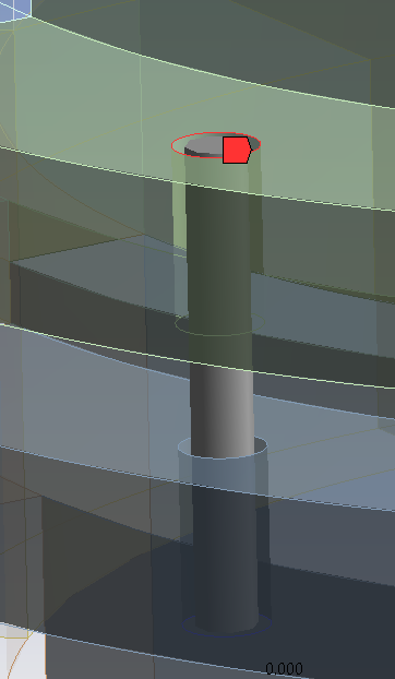
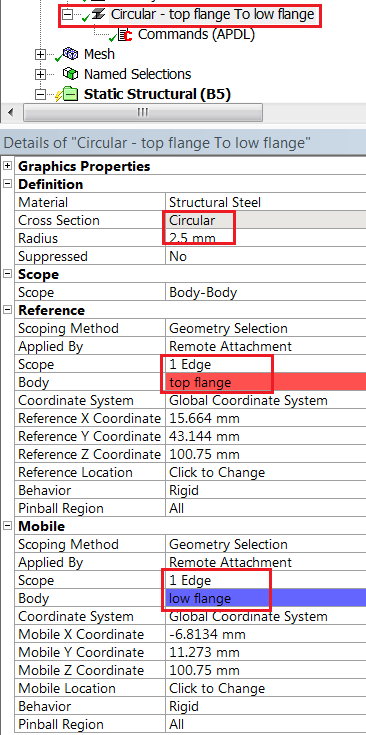
- Use Body-Body > beam connector to simulate the bolt joint; No bolt/nut geomerty required;
- Single beam 188 element created between mobile/reference geometry;
- Scope to edge or surface of bolt holes on flanges to generate beam connector;
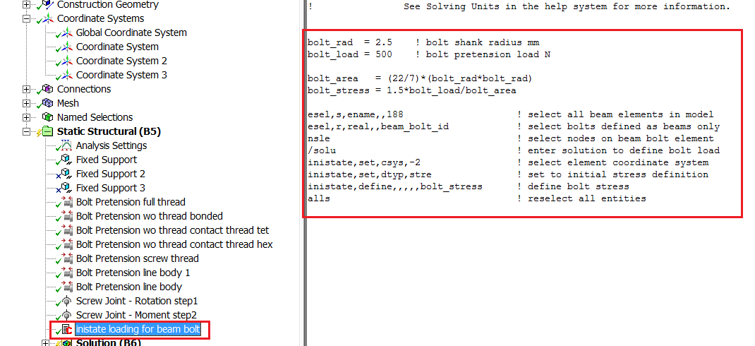
- This method cannot use bolt-pretension load directly. APDL command needs to be inserted to define the initial stress/strain induced by the bolt force.
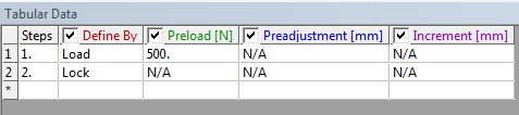
Apply Bolt Pretension Load
In the example, the bolt pretension load (500N) will be applied to bolt models except the Bolt Model 8. Select bolt shank surface (solid bolt) or edge (line bolt) to apply the load

Two load steps are required: first load step is to apply the pretension load, second is to lock the load.

Result Comparison:
The deflection of the top flange is consistent irrespective of how bolt has been modelled.
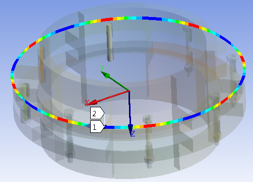

Total deformation is also axisymmetric irrespective of bolt modelling methods

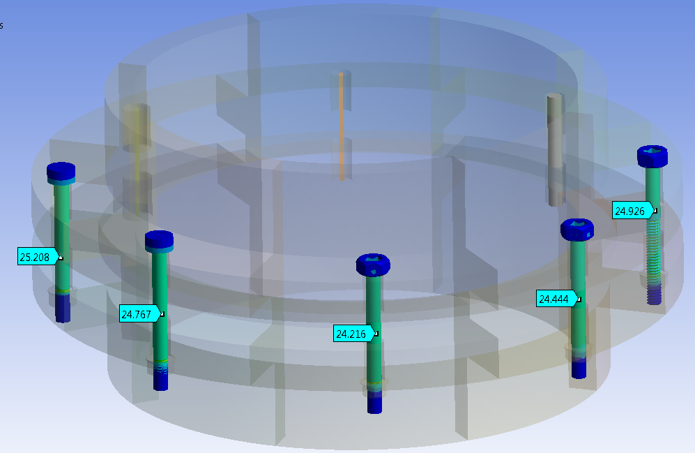
The first five bolt models (solid geometry) has predicted similar stress along the bolt shank, around 25MPa. The stress level from hand calculation is 25.6MPa (500N/19.537mm2), less than 3% difference.
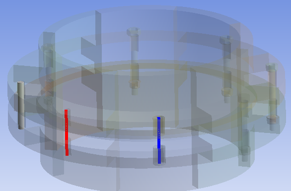
For the bolts modelled as line body, the stress in bolt shank is about 25.5MPa. (Post process using “Beam Tool”)

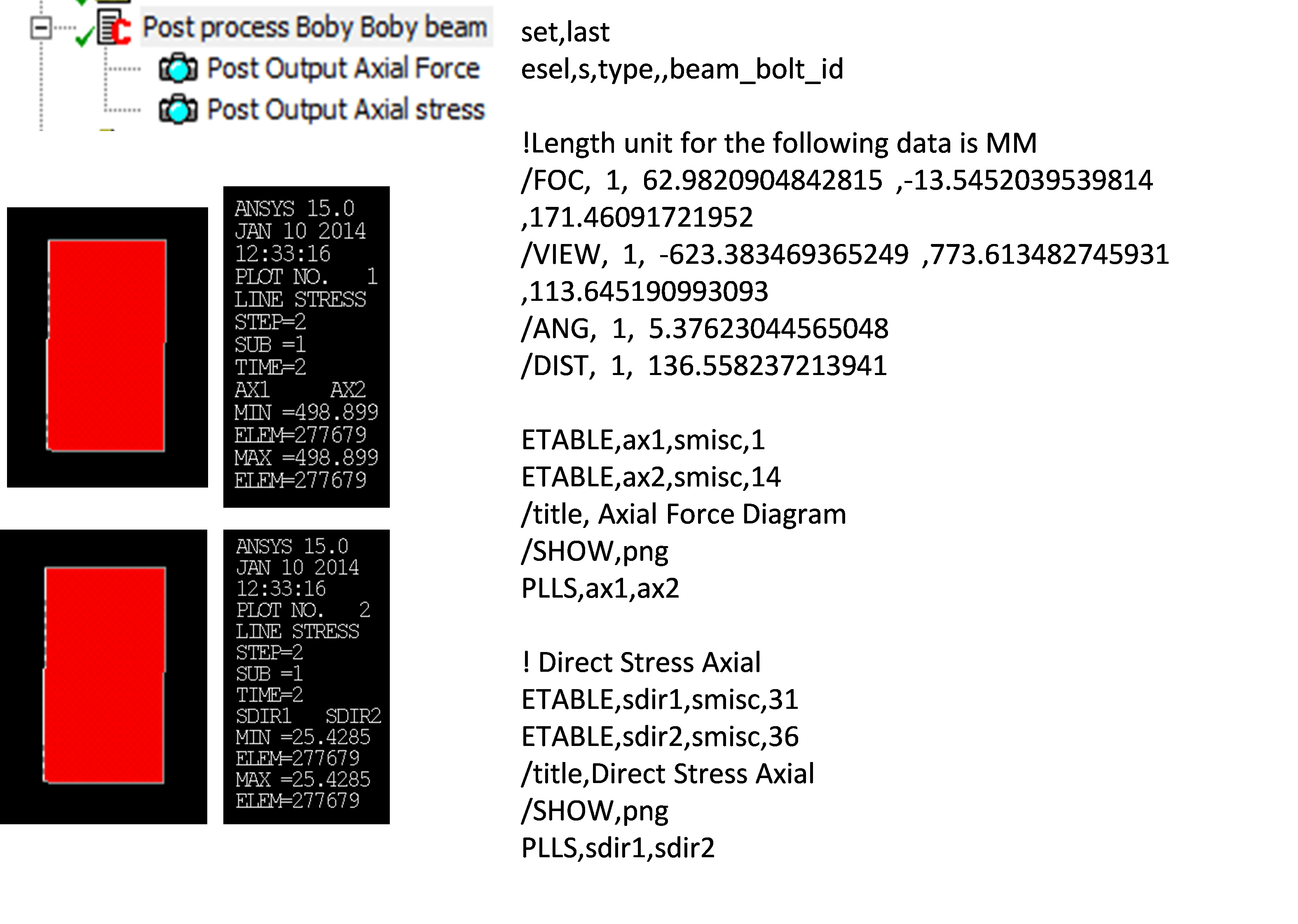
For the beam connector, using APDL commands to post process the stress result. The magnitude is about 25.4MPa.
In conclusion, users should think carefully before taking the decision on which method should be employed to model the bolt joints. In general, if the behaviour of the whole assembly is of interest, not details of stresses level in the bolt joints, the line bodies/beam connectors would be a better option as this can significantly reduce your model size.
If you need to understand the contact status between the bolt and flange and stresses, solid modelling is recommended, however some additional geometry preparation and mesh control are required. The bolt thread contact technique in ANSYS 15.0 would be highly recommended to minimise the model size and computational time.
There will be another following blog introducing more details of the bolt thread contact technique in ANSYS 15.0.