Ansys Sherlock helps automate PCB testing to accurately predict failure risks due to thermal, mechanical and manufacturing stressors using a process that is much faster than traditional simulation due to rapid ECAD translation and a component library helping you to create a complete mechanical model of your PCB.
Archives
Q&A with an Explicit Dynamics Simulation expert – using simulation to meet MIL standards for fatigue, crash and blast scenarios
We recently sat down for a quick interview with Luke Mosse, Specialist Application Engineer at LEAP to find out more about his experience from simulating blast, crash & fatigue using Ansys LS-DYNA, Ansys Mechanical and nCode software.
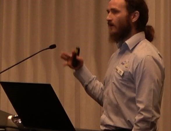
Q&A with a LEAP Expert: Why do people use SpaceClaim to prepare CAD for simulation?
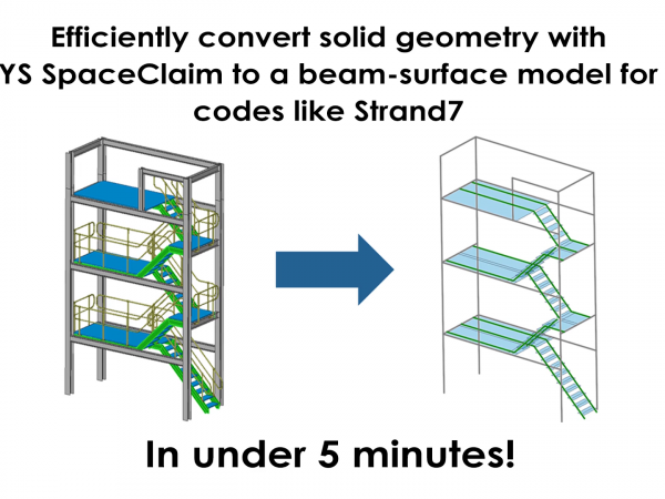
We recently sat down for a quick interview with Peter Brand, Specialist Application Engineer at LEAP to find out more about his experiences from showcasing SpaceClaim to a range of engineers from different industries across Australia & New Zealand.
Guest Blog: Using Ansys Maxwell for Motor Design in Formula Student Competition
Dramatic Accelerations in the Performance of Antenna Placement and Co-site Interference Simulations with NVIDIA GPUs
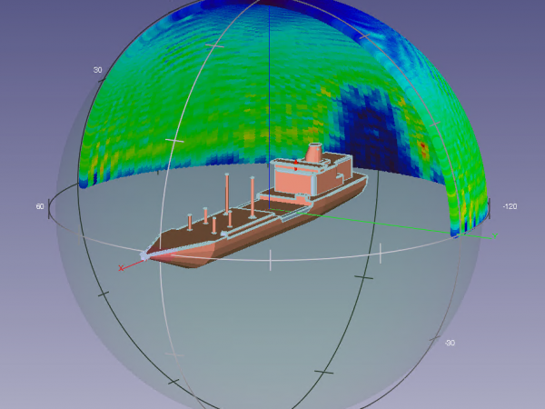
Wearable Conformal Antenna Design in Presence of the ANSYS Human Body Model
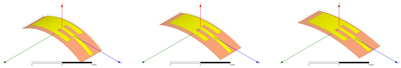
The Internet of Things has rapidly become a major industry focus with dramatic advancements in low power electronics and in wireless technology. Body-worn communication systems are now capable of detecting body motion during exercise and monitoring functions like heart rate and blood pressure. In such systems, a critical topic is how to preserve antenna performance, while achieving the requirements of small size, light weight, low power, low cost and ease of fabrication. It is also desirable to check how the antenna performance will be affected once brought into contact with the human body. The ANSYS Electronics Desktop is a tool suitable for such design applications. It is user friendly and easy to operate, leading to accurate simulation results. Planar Microstrip Patch Antenna Design in Free…
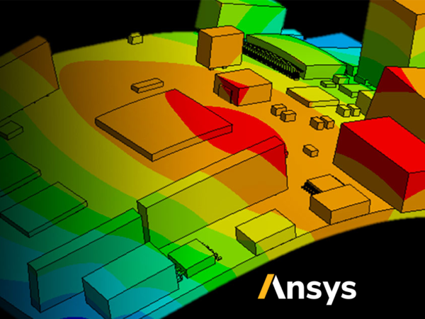
Developing Power Electronic Products in the ANSYS Electronic Desktop
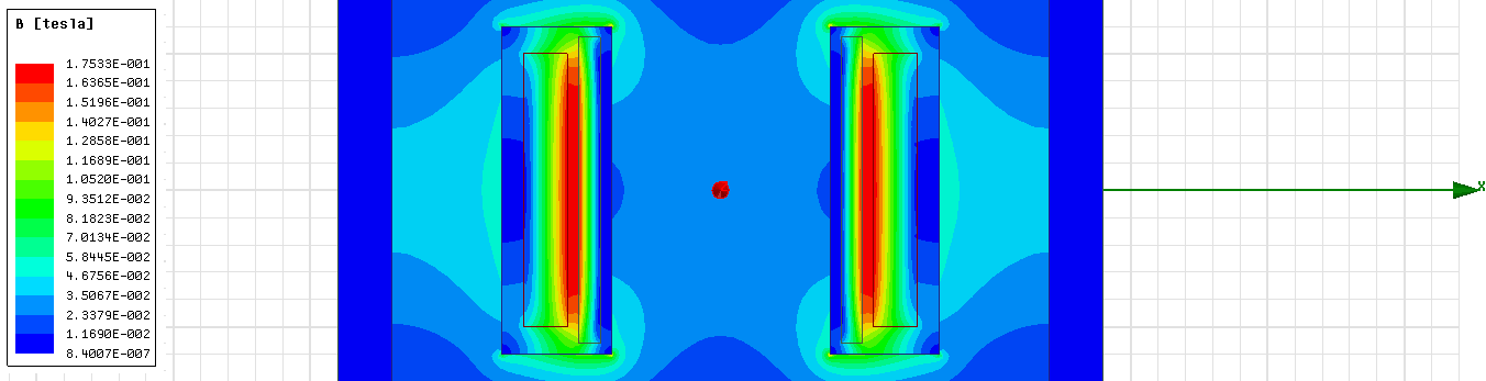
The development of power electronics products always relies on transient circuit simulation to evaluate the internal operation of the product and the effect of outside conditions in a wide variety of scenarios. With this design style in mind, circuit simulation has developed to focus on being extremely fast and parametric to allow circuit designers to run hundreds and thousands of iterations on a design per day. However, as product performance reaches ever higher and the design limitations become ever tighter, circuit simulation is starting to lack the accuracy and functionality required to predict the more expensive design metrics. Energy losses due to skin effects, nonlinearities due to saturable magnetics, trace/package coupling due to parasitics and high frequency harmonics due to fast switching semiconductors require detailed…
Error-Free Embedded Software Design as part of a Multiphysics Simulation with ANSYS
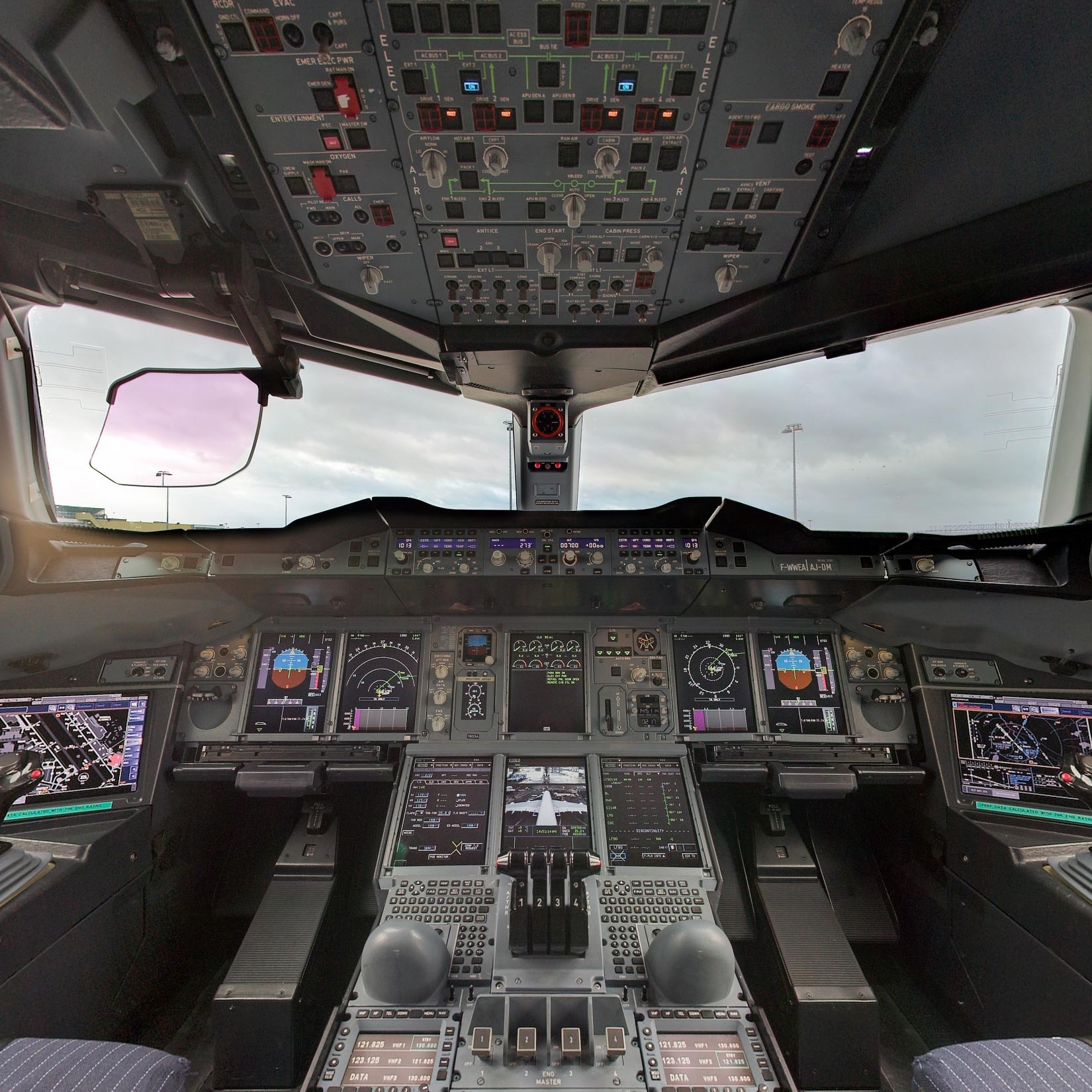
In the pursuit of ever higher performance, software is taking over a much larger responsibility for the function of the end product than ever before. A particularly dramatic example is the design of inherently unstable aircraft such as the Lockheed F-117 Nighthawk. Without the flight computers making very fine adjustments every millisecond, it would flip upside down and crash with no possibility of recovery by the pilot. This illustrates the pressing need to be able to develop software without errors and extensively test it against both theoretical and practical scenarios without leaving the engineers workstation. Software standards are already in place across a wide variety of industries to provide guidance on developing safety critical software but the actual performance of the device still depends on…
Meshing Fabricated Structures in ANSYS Mechanical using Mesh Edit

The introduction of parallel part-by-part meshing to ANSYS Mechanical 15 back in 2013 was revolutionary. Structures which took hours to mesh now wrapped up in minutes, unfortunately removing one of our favourite excuses for taking a tactical nap. One of the limitations to this new feature was the fact that Multibody parts were still meshed in serial. Given that customers in the maritime, aviation and defence industries all utilised Multibody parts to connect shell assemblies, this was a pretty big drawback. Introduced in R16 and refined in R17, ANSYS Inc have introduced a suite of tools focussed on “mesh editing” which work to enhance the workflow associated with meshing and connecting fabricated structures. Over the course of these two releases, a number of new features…
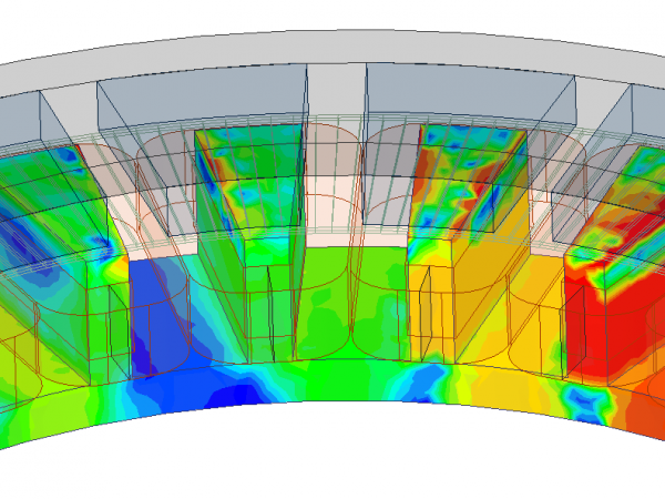
Topological Optimisation with ANSYS 17.0
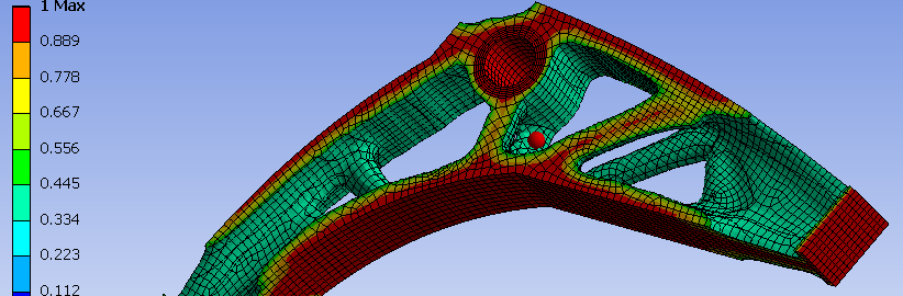
Utilising the new FREE topology optimisation ACT-extension, one can explore new innovative ways to reduce mass that were not available before. The DoE (Design of Experiments) approach may not be feasible if the design’s shape is not yet defined, while creating CAD models to capture all the potential design possibilities may be impossible. Now imagine starting with an arbitrary volume and having each element within either turned on or off to create the most optimum shape, taking into consideration the applied loads, boundary conditions, and design constraints (such as, a maximum displacement/stress limit required for the design) to achieve an overall weight reduction. In Shape Optimisation, we have constraints and objectives. Constraints define the optimisation’s bounds, while objectives are essentially the goal of the optimisation problem. In the following example, the imposed loadings on the Bell Crank must…