
The Internet of Things has rapidly become a major industry focus with dramatic advancements in low power electronics and in wireless technology. Body-worn communication systems are now capable of detecting body motion during exercise and monitoring functions like heart rate and blood pressure. In such systems, a critical topic is how to preserve antenna performance, while achieving the requirements of small size, light weight, low power, low cost and ease of fabrication. It is also desirable to check how the antenna performance will be affected once brought into contact with the human body.
The ANSYS Electronics Desktop is a tool suitable for such design applications. It is user friendly and easy to operate, leading to accurate simulation results.
Planar Microstrip Patch Antenna Design in Free Space
There are a variety of wearable antennas, such as planar dipoles, monopoles, planar inverted-Fs and microstrip patches. Microstrip antennas are planar and can be easily made onto a printed circuit board (PCB), which makes them a practical antenna type due to their low cost and easy fabrication. Figure 1 shows the structure of a planar microstrip inset fed patch antenna, where the resonant frequency is related to the width W1 and length L1 of the patch, the substrate thickness h and permittivity εr of the dielectric. The antenna is printed on a dielectric substrate with permittivity εr = 3.38 and h = 1.254mm. The antenna consists of an inset patch and a 50 Ohm microstrip feed line on the top side of the substrate, and a ground plane of 1mm thickness on its bottom side [1].
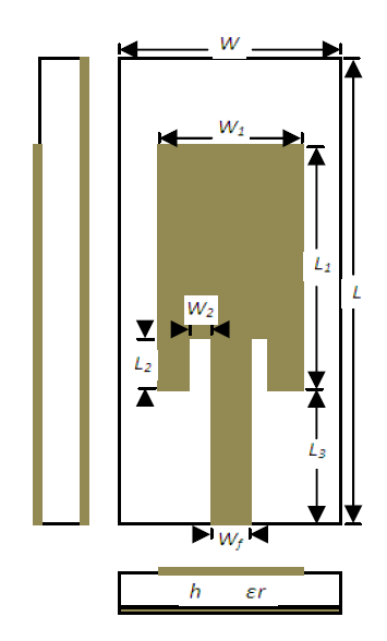
Figure 1 – Planar Inset Fed Microstrip Patch Antenna Structur
Table 1 – Antenna dimensions
The ANSYS Electronics Desktop is used to optimise the antenna dimensions so that the antenna resonates at around 2.4 GHz. Figure 2 shows the antenna model in the ANSYS Electronics Desktop. Figure 3 shows the simulated return loss of the optimised antenna in free space, and Table 1 lists its dimensions.
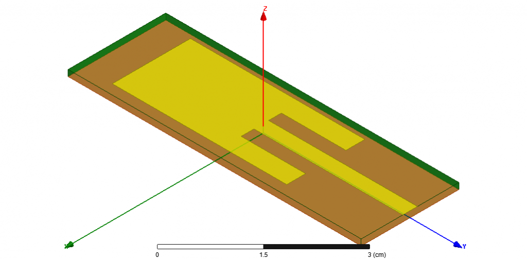
Figure 2 – Planar Inset Fed Microstrip Patch Antenna Model using the ANSYS Electronics Desktop
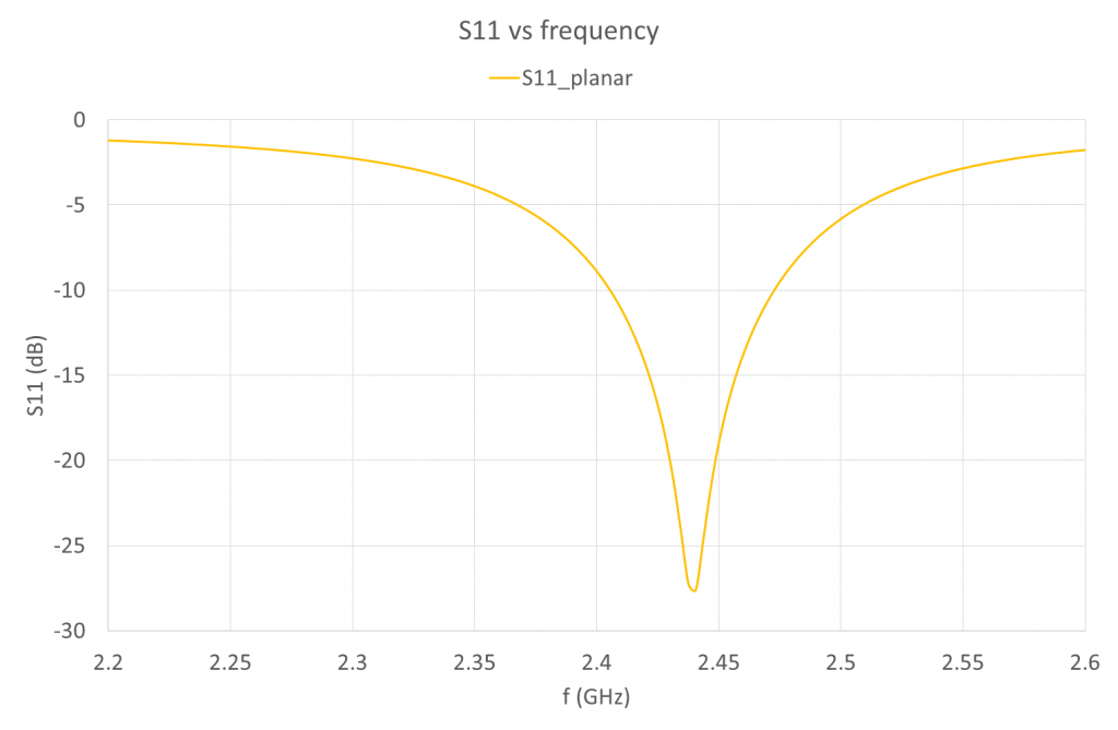
Figure 3 – Planar Inset Fed Microstrip Patch Antenna Return Loss
Wearable Non-planar Conformal Antenna Structure
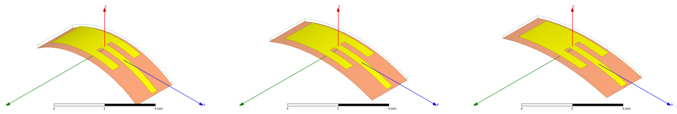
The proposed wearable antennas are designed to be worn on the exterior body and outer garments or tactical vests operating in the 2.4GHz wireless networking band. Let us suppose these antennas are to be worn on a wrist. Three different cylinders with radius R=5, 7.5 and 10cm were chosen to bend the antennas, corresponding to typical sizes of the human wrist. Figure 4 shows the conformal antenna models in the ANSYS Electronics Desktop, and Figure 5 shows the return loss of conformal antenna models.

Figure 4 – Cylindrically Curved Structures of radii 5cm, 7.5cm and 10cm
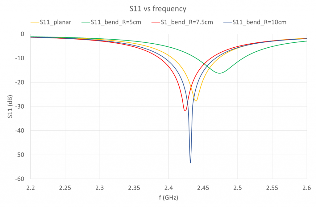
Figure 5 – Return Loss of Cylindrically Curved Structures of radii 5cm, 7.5cm and 10cm
From Figure 5, it is seen that the resonance frequencies changed from 2.44GHz (planar) to 2.47GHz (R=5cm), 2.42GHz (R=7.5cm) and 2.43GHz (R=10cm). This will give practical design guideline when choosing the operating frequency of conformed antennas.
Conformal Antenna Structure Worn on Wrist
The antenna performance while in close proximity to the human body is our main concern. The ANSYS Electronics Desktop provides a human body model library which makes it convenient to add a human body 3D component. Figure 6 shows the model of a conformal antenna worn on wrist in the ANSYS Electronics Desktop.
Figure 7 shows the return loss variation with placing conformal antennas on human wrist. The dotted lines represent conformal antennas in free space, while the solid lines represent those worn on wrist. With antennas closer to human body, the resonance damps a little, and the resonant frequency has minor shift. Figure 8 shows the gain pattern change at 2.4GHz after placing the conformal antenna of curving radius 5cm on wrist, letting the antenna centre placed on the original point of coordinate system. To investigate the gain pattern in more details, Figure 9 shows the gain pattern with the antenna overlay. After placing the antenna on human wrist, the antenna radiation is more focused in the positive half space (z>0), since in the negative half space (z<0) the radiation is mostly blocked by the wrist beneath the antenna.
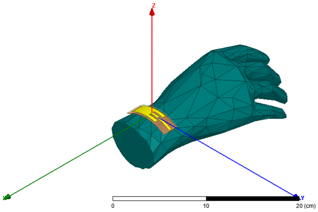
Figure 6 – Conformal Antenna Structure Worn on Wrist
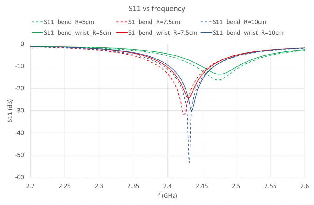
Figure 7 – Return Loss of Cylindrically Curved Structures of radii 5cm, 7.5cm and 10cm before and after being placed on wrist
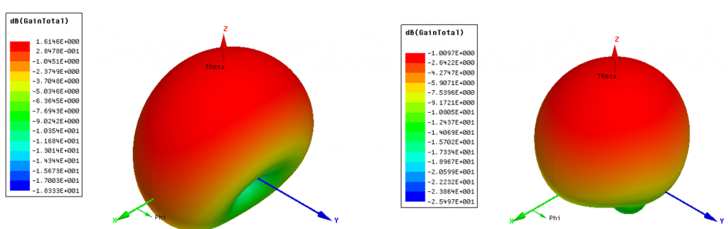
Figure 8 – Gain of Cylindrically Curved Structures of radii 5cm before and after being placed on wrist
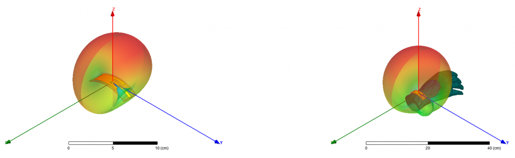
Figure 9 – Gain of Cylindrically Curved Structures of radii 5cm before and after being placed on wrist with antenna overlay
This example demonstrates the power of the ANSYS Electronics Desktop for efficiently designing wearable antennas and simulating the impact of real world scenarios. The ANSYS Electronics Desktop provides an accurate calculation and visual elaboration on the antenna performance, such as return loss, resonant frequency and radiation performance. It helps us to reach the design target by not only optimising the performance within a variety of variables, but also predicting the behaviour of whole system.
In conclusion, the ANSYS Electronics Desktop provides a highly efficient solution for high fidelity antenna design and optimisation.
Hongmei Fan
ANSYS Applications Engineer (Electromagnetics)
References
[1] Emad Shehab Ahmed: Wearable Conformal Antennas for 2.4 GHz Wireless Body Area Networks, TELKOMNIKA, vol. 11, no. 1, 2013, pp. 175-180.